Supplied By www.heating spares.co Tel. 0161 620 6677
44
13 Servicing
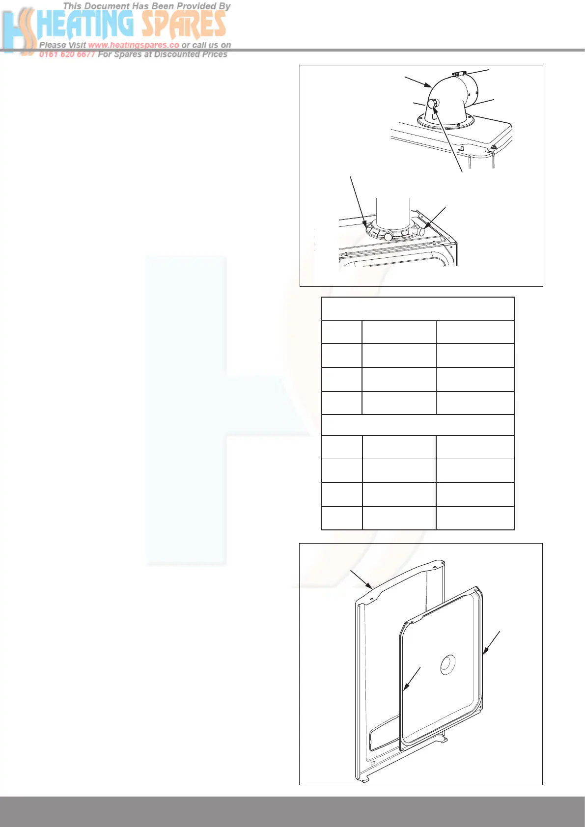
13.7 Combustion Check
With the appliance operational connect the CO
2
combustion
analyser to the test point, see diagram 13.9.
IMPORTANT: Remember to replace the cap on
completion of the test.
Check the burner %CO
2
, at maximum rate(open a hot water
tap fully to generate a demand). The values are shown in the
“CHECK” column of the table and if the reading falls within
the range, disconnect the analyser, fit the test point cap and
return to functional checks - gas rate.
If adjustment is required remove the front and inner casing
panels, see diagram 13.1. Taking care not to touch any
internal components, proceed as follows:
Press the “reset” button on the controls fascia, release
and immediately pr
ess and hold in the “+” button. After
approximately 5 seconds “Hi” will be displayed. Pressing
the mode button when “Hi” is selected will force the boiler
to maximum rate, the display will flash between “Hi” and the
“default display” this will indicate the boiler has been forced
to maximum.
Adjust the %CO
2
to the value shown in the “SETTING”
column of the table with the throttle, see diagram 12.5.
(Rotate anti-clockwise to increase).
To exit the check sequences press the “mode” and “+”
buttons simultaneously, this will reset the boiler to the default
display.
Check the burner % CO
2
at minimum rate is as shown in the
“CHECK” column of the table.
Press the “reset” button on the controls fascia, release
and immediately press and hold in the “+” button. After
approximately 5 seconds “Hi” will be displayed. Pressing the
“+” or “-” buttons will cycle between “Hi” and “Lo”. Pressing
the mode button when “Lo” is selected will force the boiler
to minimum rate, the display will flash between “Lo” and the
“default display” this will indicate the boiler has been forced
to minimum.
Adjustment of the %CO
2
at minimum rate is very coarse
so carefully adjust the %CO
2
to the value shown in the
“SETTING” column of the table with the offset adjustment,
see diagram 12.5 and %CO
2
Table (Rotate clockwise to
increase).
To exit the function press the “mode” and “+” buttons
simultaneously, this will reset the boiler to the default display.
13.8 Gas Rate Adjustment
This appliance incorporates a pre-mix burner and cannot be
adjusted, however, it is acceptible to set the combustion rate
with a gas analyser as described in section 13.7.
13.9 Inner Casing Panel Seal check
Check the condition of the seal, if worn or damaged remove
the seal and thoroughly clean the casing surface before fitting
the new seal, see diagram 13.10.
Refit the inner casing panel.
NOTE: Ensure the seal is fitted correctly giving an airtight
joint.
13.10 Service Completion
On completion of the service the “Benchmark” Service
Record should be completed.
FLUE ELBOW
COMBUSTION
ANALYSER
SAMPLE
POINT
VERTICAL FLUE
ADAPTOR
Diagram 13.9
13566
10063
INNER
CASING
PANEL
FRONT
CASING
PANEL
SEAL
Diagram 13.10
MODEL
24cxi
30cxi
38cxi
G31 BURNER % CO2
CHECK
(case on)
SETTING
(case off)
9.2 to 10.2
10.0 to 11.0
9.2 to 10.2
10.0
10.5
9.8
+ 0.0
- 0.9
+ 0.3
- 0.7
+ 0.2
- 0.8
MODEL
24cxi
30cxi
38cxi
G20 BURNER % CO2
CHECK
(case on)
SETTING
(case off)
8.5 to 9.6
8.5 to 9.6
8.5 to 9.3
9.1
9.1
8.8
+ 0.2
- 0.5
+ 0.2
- 0.5
+ 0.2
- 0.5
 Loading...


