screen. Please choose a proper way according to your usage.
Method 1: For use without the Glux signal divider: Link the LED screen with
VSP-F2L4 controller by signal cable. It means that signal is transmitted to the LED
screen directly from the controller’s output port (OUT1~OUT4).
Method 2: With signal divider. Transmit signal from VSP-F2L4 controller’s output
port “OUT1~OUT4”to SDV signal divider’s input port “SIG IN” by CAT6 Ethernet
cable. The signal will be transmitted from SDV signal divider’s interface A1~A4,
B1~B4 to LED screen by signal cable.
Method 3: With signal divider. Transmit signal from VSP-F2L4 controller’s optical
port OUT1~OUT2 to SDV signal divider’s optical input port “ IN” by optical fiber
cable. And then signal will be transmitted from SDV signal divider’s interfaces
A1~A4, B1~B4 to LED screen by signal cable.
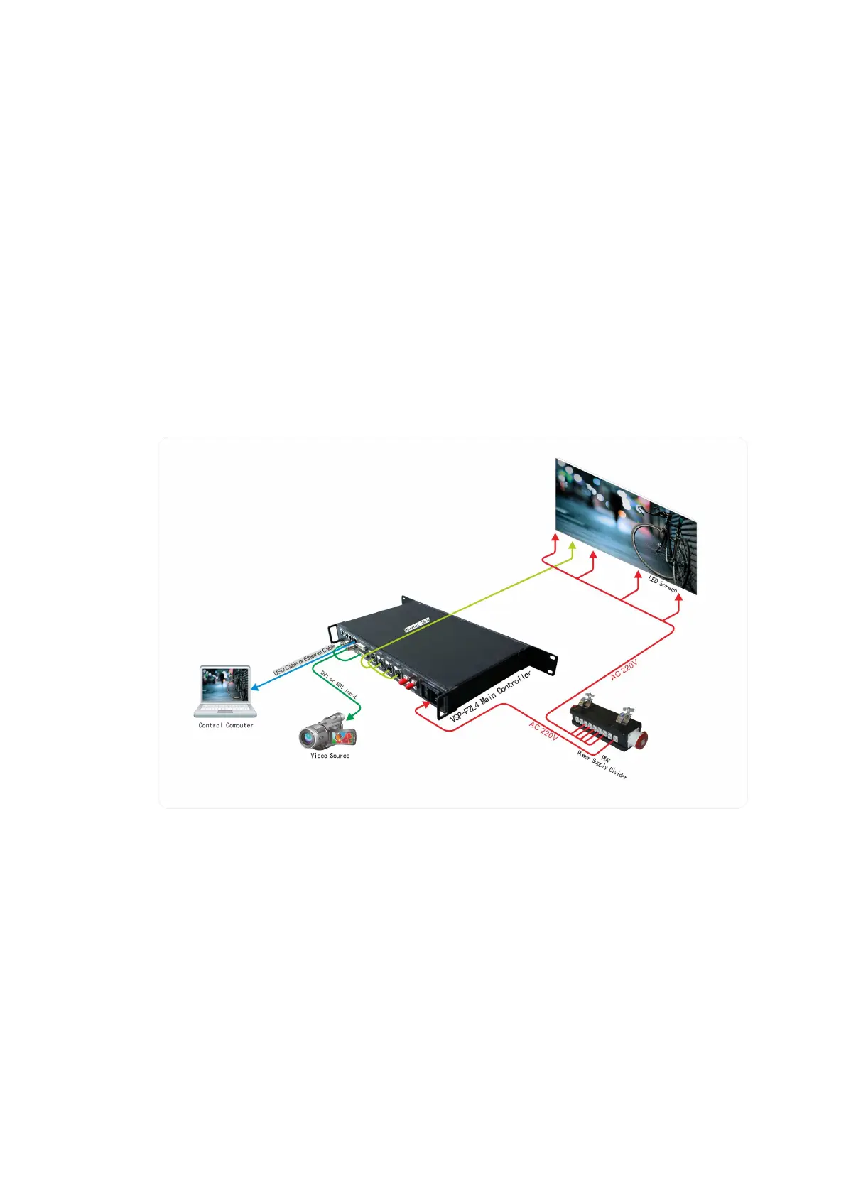
Three kinds of connection modes are showed as below:
System signal connection method 1 (Transmission distance
≤
120m)
Signal be transmitted from controller to LED screen directly
 Loading...