Technology for safety
4
D1000 series - Intrinsically Safe Isolators
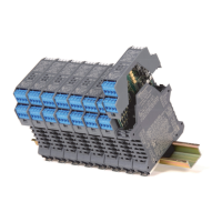
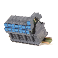
D1000 Power Bus Enclosure
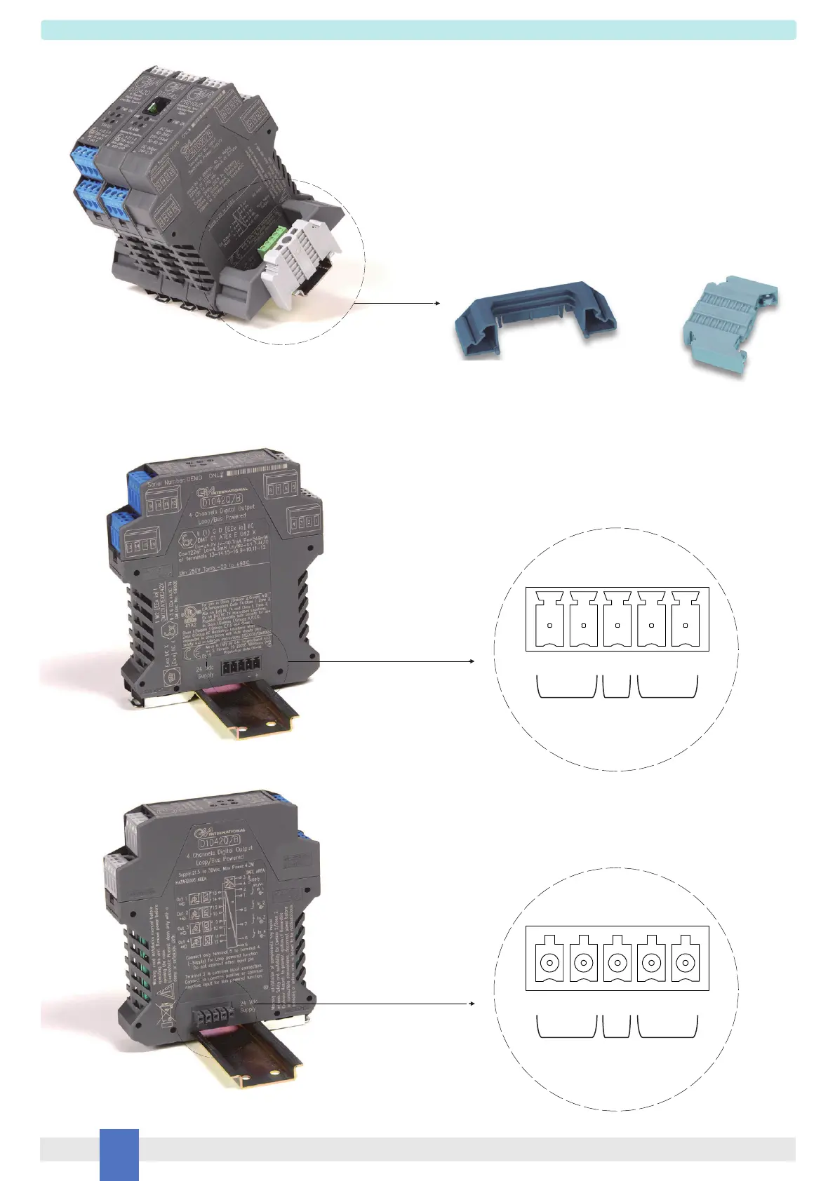
Module Enclosure with
Power Bus Connector female Side
Module Enclosure with
Power Bus Connector male Side
Power Supply Voltage 12-24 Vdc can be applied to the module,
by connecting directly the voltage to the plug-in Terminal Block of
each module, or via the Power Bus System. The system consists
of a standard DIN-Rail and modules with Bus Connectors (female
on one side and male on the other). The maximum allowed powering
capacity is 8 Amp. It is always possible to remove modules, without
disconnecting the bus connection. When the Power Bus is used,
Supply Contacts on Terminal Blocks are omitted to avoid accidental
short circuits on the Power Bus. Cumulative Fault Alarm indication is
provided on the Bus connection. This signal is in common with the
supply and drives a remote indication, typically through a D1091S
module.
Power
Supply
DIN-Rail Anchor for terminal block
Side of the Power Bus
DIN-Rail Stopper
B+ A - FLT - +
Modbus Fault
Modbus
+ - FLT A- B+
Power
Supply
Fault