7
D5294 - 5 A SIL 3 NO contact Relay Out Module for NE or F&G/ND Load with full diagnostic and Modbus G.M. International ISM0123-14
Configuration
For configuration of T-proof relays testing, some DIP Switches are located on component side of pcb. These switches allow the T-proof relays test (SW1 dip-switch: 1-2-3-4 set “ON” and
see “Testing procedure at T-proof” section for more information).
WARNING: after T-proof test, dip-switch 1-2-3-4 must be set
to “OFF” position for normal operation.
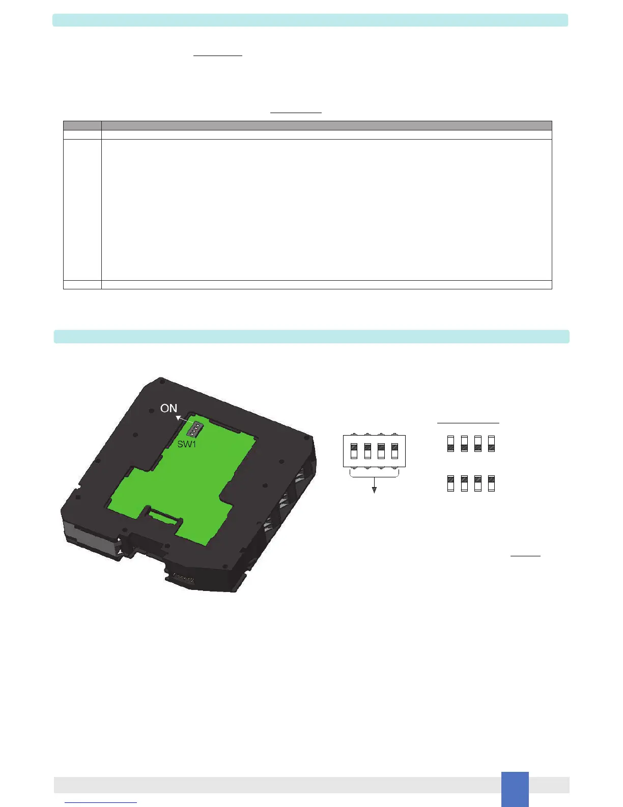
SW1 Dip switch configuration
123
4
ON
T-proof relays enable
123
123
Normal Operation
ON ON
OFF
ON
OFFOFF
T-proof relays (dip1 = relay1;
dip2 = relay2; dip3 = relay3;
dip4 = relay4)
4
OFF
ON
4
This is factory settings
The proof test shall be performed to reveal dangerous faults which are undetected by diagnostic. This means that it is necessary to specify how dangerous undetected faults, which
have been noted during the FMEDA, can be revealed during proof test.
Before of specific Proof test, execute the following general proof test: connect the load supply lines to terminal blocks “15” (for +/AC) and “16” (-/AC) and the NE or F&G / ND output load
to terminal blocks “13” (as the positive terminal) and “14” (as the negative terminal); finally, connect the DCS/PLC signal to input channel terminal blocks “1” (as the positive terminal) and
“2” (as the negative terminal). Then, verify the input to output functionality: the output NE load is Normally Energized by supplying the input channel, while shutdown of the input channel
de-energizes (safe state) the load; the output F&G / ND load is Normally De-energized by shutdown of the input channel, while supplying the input channel energizes (safe state) the
load. The channel functionality must be verified for a min to max input voltage change (21.6 to 27.6 Vdc).
Then, disconnect the load supply lines from terminal blocks “15” - “16” and the output load from terminal blocks “13” - “14”. Then, connect an ohmmeter (Ohm. A) between terminal blocks
“15” - “13” and another one (Ohm. B) between terminal blocks “16” - “14”. The specific Proof test consists of the following steps:
Testing procedure at T-proof
Steps Action
1 Bypass the safety-related PLC or take other appropriate action to avoid a false trip when removing the unit for test.
2 1. Do not supply the input channel (terminals “1”-“2”) of the unit under test and verify that ohmmeters Ohm. A and Ohm. B measure absence of ohmic
continuity (i.e. both +/AC and -/AC load lines are interrupted because all NO contacts are open: 1
st
requisite is verified). For both ohmmeters Ohm. A
or Ohm. B, these measures could also be true if only one of two relay contacts in parallel is open and other is blocked (for welding) into open position:
this will be verified by testing the channel when input is supplied, as described in the point 3 of this procedure. Instead, the presence of ohmic continuity
measured by ohmmeter Ohm. A or Ohm. B, implies that at least one relay contact is blocked (for welding) into closed position: this could be verified
disassembling and individually testing each relay.
2. Supply the input channel (terminals “1”-“2”) of the unit under test and verify that ohmmeters Ohm. A and Ohm. B measure presence of ohmic continuity
(i.e. both +/AC and -/AC load lines are not interrupted because NO contacts are closed: 2
nd
requisite is verified). The absence of ohmic continuity
measured by ohmmeter Ohm. A or Ohm. B implies that two relay contacts are blocked (for welding) into open position.
3. Supply always the input channel (terminals “1”-“2”) of the unit under test in order to verify if a single contact is blocked (for welding) into open position.
Considering the measures of ohmmeter Ohm. A, set ON internal SW1 DIP-switches (n°1 or 2) to put in short circuit one relay coil at a time (starting with
the 1
st
coil by DIP-switch n°1, then going on with the 2
nd
coil by DIP-switch n°2), verifying that ohmic continuity is always present between terminals
“15” - “13”. Considering the measures of ohmmeter Ohm. B, set ON internal SW1 DIP-switches (n°3 or 4) to put in short circuit one relay coil at a time
(starting with the 3
rd
coil by DIP-switch n°3, then going on with the 4
th
coil by DIP-switch n°4), verifying that ohmic continuity is always present between
terminals “16” - “14”. In these situations, the absence of ohmic continuity implies that a relay contact (the one with energized coil because the other is
de-energized, being its DIP-switch set ON) is blocked (for welding) into open position.
3 Remove the bypass from the safety-related PLC or restore normal operation inserting the unit.
This test reveals almost 99 % of all possible Dangerous Undetected failures in the relay module.
 Loading...