8
D5294 - 5 A SIL 3 NO contact Relay Out Module for NE or F&G/ND Load with full diagnostic and Modbus G.M. International ISM0123-14
Diagnostic Application for D5294S - SIL 2 Fault Relay Output with NO contact
Functional Safety Manual and Applications
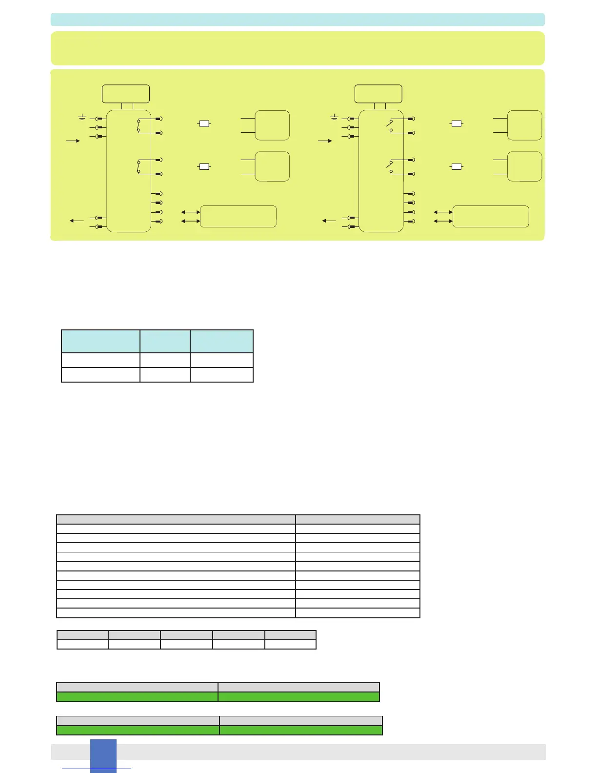
De-energized to trip operation - presence of fault Normal state operation - absence of fault
Description:
In this application D5294S module monitors Load Power DC/AC line (Pins 15-16) and Out NE or F&G/ND Load (Pins 13-14) by internal diagnostic circuits and uses Fault Out 1 or
Fault Out 2 NO contact to signal presence of faults on them. At pages 11-12 it’s shown how to configure and to monitor the diagnostic operation parameters (as fault conditions), by
means of Modbus IN/OUT protocol with RS485 connection (Pins 5-6) or by PPC5092 adapter and SWC5090 related software. When diagnostic supply is connected to
Pins 9(+) - 10(-), the power green led is ON. NE or F&G/ND load connected on Pins 13-14 is controlled by input signal Pins 1-2 from PLC/DCS.
As shown in the diagram, Fault Outputs (Out 1 or Out 2) contact can be connected to Safety PLC Input or used to (de-)energize a load by switching its supply lines.
Fault relay contacts (Pins 3-4 for Fault Out 1 or 11-12 for Fault Out 2) are closed in normal state operation, that is absence of faults, so that diagnostic load is normally energized.
This function is valid if “inverted fault relay” parameter is set to “0” or its field is not checked as explained at pages 11-12. In case of faults detected by internal diagnostic circuits,
de-energized to trip operation is applied to fault relay and its contacts become open, so that diagnostic load is de-energized.
The following table describes the status (open or closed) of each fault output contact in absence or presence of faults detected by internal diagnostic circuits:
Safety Function and Failure behavior:
D5294S is considered to be operating in Low Demand mode, as a Type B module, having Hardware Fault Tolerance (HFT) = 0.
The failure behaviour of SPST fault relay output with NO contact and without “invert fault relay” condition
by the following definitions:
Fail-Safe State: it is defined as the diagnostic relay output being de-energized, with open contact and de-energizing related load;
Fail Safe: this failure causes the system to go to the defined Fail-Safe state without a process demand;
Fail Dangerous: failure mode that does not respond to a demand from the process (i.e. being unable to go to the defined Fail-Safe state), so that the diagnostic relay output
remains energized or relay contact keeps closed (energizing related load) because of diagnostic measure error more than +/-20% of correct value or due to contact welding;
Fail “No Effect”: failure mode of a component that plays a part in implementing the safety function but that is neither a safe failure nor a dangerous failure; in particular,
diagnostic measure error is less than +/-20% of correct value. When calculating the SFF, this failure mode is not taken into account;
Fail “Not part”: failure mode of a component which is not part of the Safety function but part of the circuit diagram and is listed for completeness. When calculating the SFF,
this failure mode is not taken into account. The input and relay blocks failures are classified as “Not Part” failures.
As the module is supposed to be proven-in-use device, therefore according to the requirements of IEC 61511-1 section 11.4.4, a HFT = 0 is sufficient for SIL 2 (sub-) systems includ-
ing Type B components and having a SFF equal or more than 60%.
Failure rate date: taken from Siemens Standard SN29500.
Failure rate table:
Failure rates table according to IEC 61508:2010 Ed.2 :
This type “B” system has SFF = 70.54% 60% and HFT = 0, which is sufficient to get SIL 2 in accordance with the requirements of IEC 61511-1 section 11.4.4 during
a proven-in-use assessment.
PFDavg vs T[Proof] table (assuming Proof Test coverage of 99%), with determination of SIL supposing module contributes 10% of total SIF dangerous failures:
PFDavg vs T[Proof] table (assuming Proof Test coverage of 99%), with determination of SIL supposing module contributes >10% of total SIF dangerous failures:
Operation Fault Out 1
Pins 3-4
Fault Out 2
Pins 11-12
Normal (absence of fault) Closed Closed
Trip (presence of fault) Open Open
Failure category Failure rates (FIT)
dd
= Total Dangerous Detected failures 0.00
du
= Total Dangerous Undetected failures 133.49
sd
= Total Safe Detected failures 0.00
su
= Total Safe Undetected failures 319.66
λ
tot safe
= Total Failure Rate (Safety Function) = λ
dd
+ λ
du
+ λ
sd
+ λ
su
453.15
MTBF (safety function, single channel) = (1 / λ
tot safe
) + MTTR (8 hours) 251 years
no effect
= “No effect” failures 215.35
not part
= “Not Part” failures 559.70
λ
tot device
= Total Failure Rate (Device) = λ
tot safe
+ λ
no effect
+ λ
not part
1228.20
MTBF (device, single channel) = (1 / λ
tot device
) + MTTR (8 hours) 92 years
T[Proof] = 1 year T[Proof] = 17 years
PFDavg = 5.86 E-04 - Valid for SIL 2 PFDavg = 9.96 E-03 - Valid for SIL 1
T[Proof] = 5 years
PFDavg = 2.93 E-03 - Valid for SIL 2
T[Proof] = 20 years
PFDavg = 1.17 E-02 - Valid for SIL 1
D5294S
9 +
10 -
Diagnostic Supply
24 Vdc
3
4
1
2
5
6
or
Safety
PLC
Input
MODBUS
IN/OUT RS485
A-
B+
11
12
or
Safety
PLC
Input
14
13
16
15
Load Power
DC/AC
Out NE or
F&G/ND Load
D5294S
9 +
10 -
Diagnostic Supply
24 Vdc
3
4
1
2
5
6
or
Safety
PLC
Input
MODBUS
IN/OUT RS485
A-
B+
11
12
or
Safety
PLC
Input
14
13
Fault Out 2
Fault Out 1
Fault Out 2
Fault Out 1
Input signal from PLC/DCS Input signal from PLC/DCS
21
16
15
Load Power
DC/AC
21
Out NE or
F&G/ND Load
Energized load
Energized load
Energized load
Energized load
λ
sd
λ
su
λ
dd
λ
du
SFF
0.00 FIT 319.66 FIT 0.00 FIT 133.49 FIT 70.54%
 Loading...