1 0991 486
EN
-
29.09.2016
ENG
DLV
VALVE MANUAL
I
NSTALLATION
,
U
SE AND
M
AINTENANCE
5 / 11
DLV are manifactured in different sizes and can be used for the following range(see the tab. 1).
Type
Max
interv.flow
Nominal
flow
Working
press.
Working
temp.
Viscosity Tens.DLV Power
Emerg.
Pw.
l/min bar °C cSt Vdc
Vac W Vdc
DLV A3 – ¾”
45 8 - 45
12 - 45 5 - 70
14-290
(ISO VG 46
I≈120)
24-12
48-12
80-12
90-12
110-12
180-12/24
110
220
230
30
12 24
DLV A3 - 1” ¼
210 15 - 210
30
DLV A3 - 1” ½
430 25 - 430
30
DLV A3 - 2”
600 30 - 600
45
Tab. 1
1.2 DELIVERY PACKAGING
Upon picking up the material,before signing the delivery,be care the goods match the packing list and the order
list.
The packing list should includes:
- Installation use and maintenance manual
- DLV device (factory assembled)
- Connection fittings
- Cartboard box
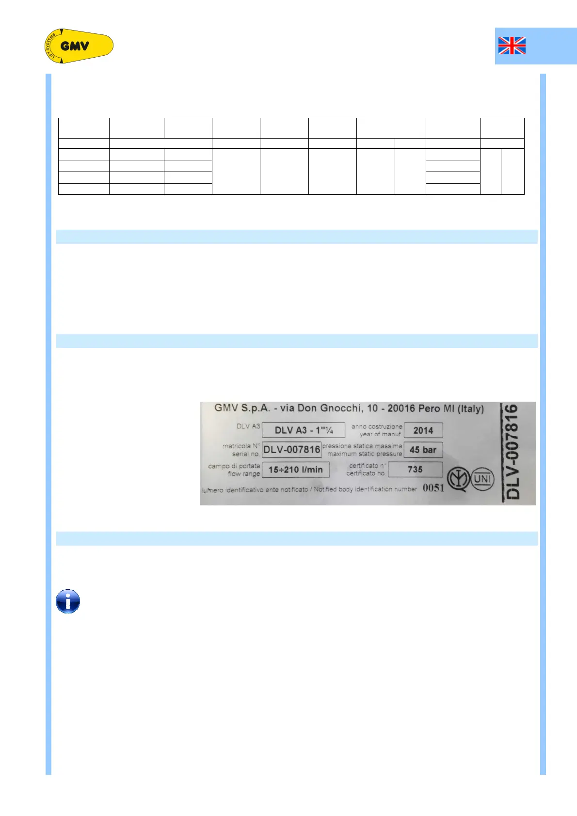
1.3 IDENTIFICATION PLATE
The indentification plate with the main factory data (see picture below), is directly placed on DLV.
The plate should include:
- Type of DLV device
- Serial number
- Year manifacturing
- Flow range
- Max static pressure
1.4 THE FLUID
The hydraulic fluid is very important for an hydraulic lift
Especially in systems with medium or intensive traffic,choosing a good fluid increases the temperature range of
comfortable working and enhances the service life of the components.
When we choose the fluid we must take into account both the characteristics of the elevator
(temperature , power unit ventilation room, amount of trafic) and the characteristics of the fluid
(temperature-viscosity).In case of replacement,follow the local pollution.Waste should be placed in a
proper box to protect the environment.