1 0991 486
EN
-
29.09.2016
ENG
DLV
VALVE MANUAL
I
NSTALLATION
,
U
SE AND
M
AINTENANCE
9 / 11
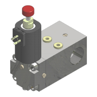
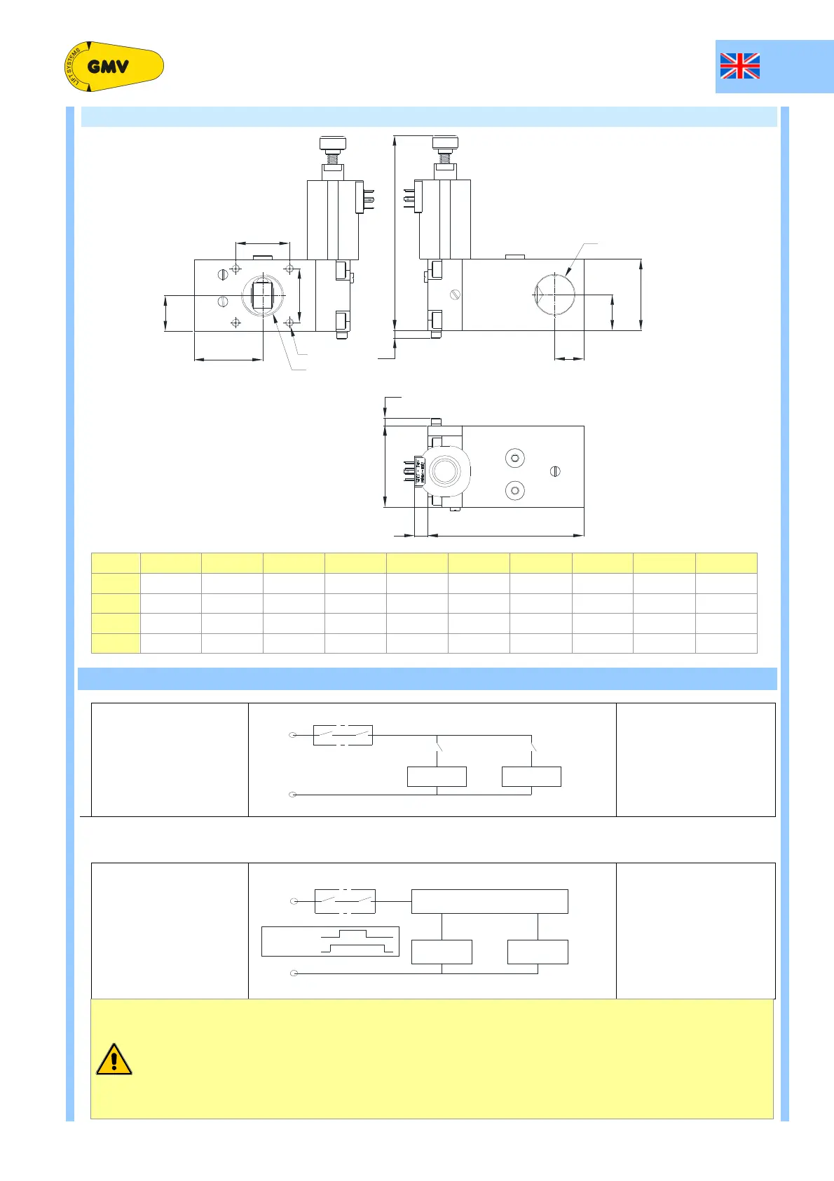
3.2 DIMENSIONS
H
T
B
A
H
VH
B
B
A
B
D
B
B
A
A
A
A
F
B
F
M8x1.25
D
A
C
VB
DLV A B C H H
T
D
A,
D
B
A
A,
A
B
B
A
B
B
A
F,
B
F
¾”
120 54 ≈6,5 54 175 ¾” G 26 48 19
1” ¼
153,5 80 ≈13 70 192 1” ¼ G 35 67,5 28,5 53
1” ½
185 90 ≈9 90 212 1” ½ G 45 73 32 -
2”
204 90 ≈15 115 237 2” G 57,5 89,25 39,5 -
4 ELETTRICAL CONNECTIONS
Mode 1
E N 8 1 - 2
V M D D L V A 3
+
-
2
Contemporaneous
EN81-2 CD LD
Safety chain Car door safety Landing door safety
Mode 2
E N 81-2
V M D D LV A 3
O N + 1 s
O FF
O N
O FF + 2 s
-
+
3
C O NTR O LLER
D LV A 3
V M D
O N
O F F
O N
O F F
Timed
INSTALLATION NOTES
Mode 1:to correctly install the DLV A3 on the valves 3010, 3100, GEV or similar, the following
devices (if presents) must be mounted, or transferred on the DLV:
- Pressure overload (installation on the DLV A3 optional if Mode 2)
- Pressure transducer (installation on the DLV A3 optional if Mode 2)
- Pressure gauge and pressure gauge inspection EN (installation on the DLV A3 recommended)
All above to provide a correct reading of the pressure value.