1 0991 486
EN
-
29.09.2016
ENG
DLV
VALVE MANUAL
I
NSTALLATION
,
U
SE AND
M
AINTENANCE
7 / 11
2. Timed
The DLV A3, respect to the main downward solenoid valve VMD, is energized about 1 second before and
de-energized almost 2 seconds after the arrival at landing.
In this way the DLV A3 is not an element working to control the lift and consequently does not require any
kind of monitoring. Its correct working can be verified during the standard maintenance operations every 6
months.
A3 intervention state of DLV
In the shaft must be present a system (ex. two contacts/switches) able to detect the unintended movement of
the car with open doors in up or down direction.
During an unintended movement in down direction, when the unintended movement is detected, the system
de-energize the DLV A3 valve to let it close and stop the lift.
During an unintended movement in up direction the system must switch off the motor/pump to stop this
movement. Consequently the valve will stop the car.In every case,after this phase,the system should go out of
service and it should be restored only by an authorized and properly trained person. The system which detects
the unintended movement and energizes the stopping device can be the existing one just used to define the
opening doors zone. The intervention zone, according to the EN 81-2, must be at maximum ± 200 mm from the
landing
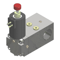
2.2 HYDRAULIC SCHEME
Here below (pict.3) follows the DLV hydraulic scheme to show the placing of DLV,between the main valve and
the jack.
Legend
Pict. 1
PT Pressure trasducer
DLV Non return pilot-operated valve
R/S Shut off valve/Silencer
VC Check valve
ISP Inspection pressure gauge fitting
MAN Pressure gauge
Pmax Maximum pressure switch
Pmin Minimum pressure switch
OLD Overload pressure switch
J Jack
[F] DLV connection main valve side
[H] DLV connection main jack side
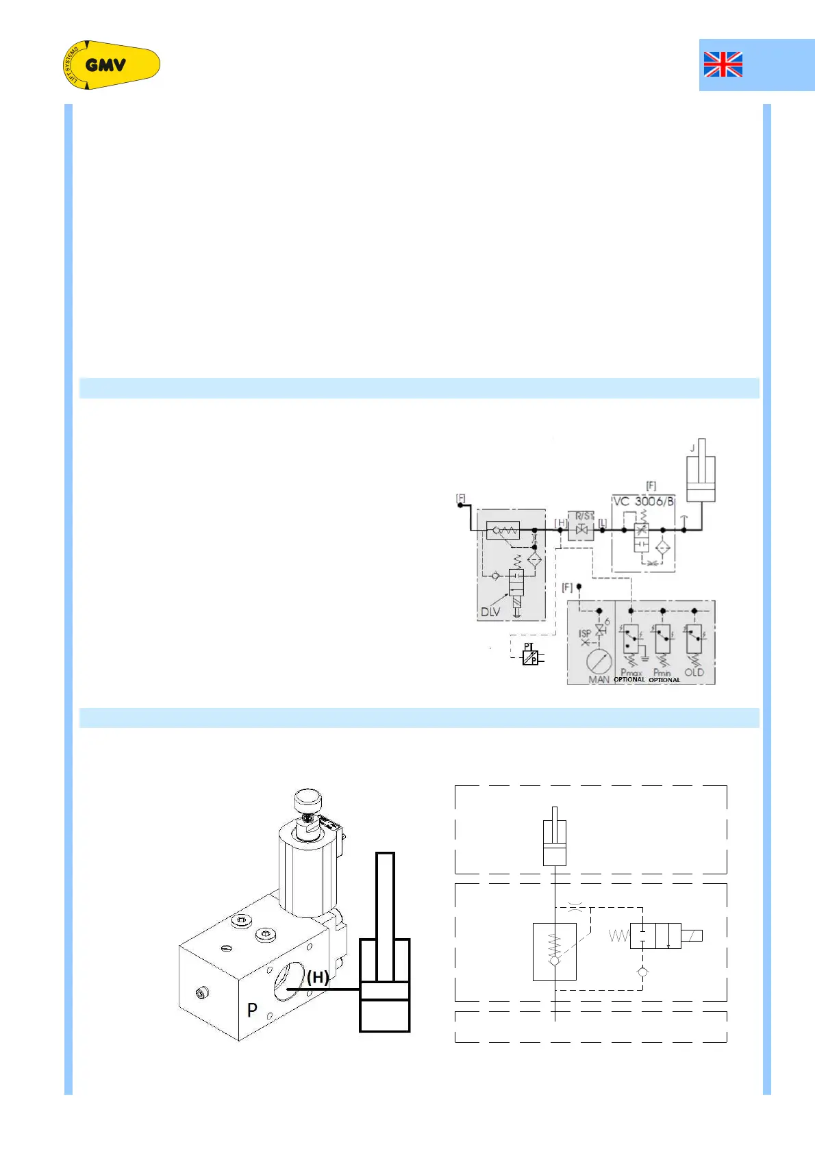
2.1 SEMPLIFIED HYDRAULIC SCHEME
DLV A3 Non return pilot valve
VAL Main valve
J Jack
VAL
DLV A3
J
[H]
[F]