EasyManuals Logo

Go Power GP-ISW-1500 User Manual

Default Icon
42 pages
To Next Page IconTo Next Page
To Previous Page IconTo Previous Page
Page #16 background imageLoading...
Page #16 background image
[page 16] | gpelectric.com
Cable to
GP-ISW Unit
FM
80
30 Amp
Breaker
Fuse
Block
Battery Bank
MC4 Connector
Refrigerator
Vent Cover
100W or 160W
Solar Panel
Mate 2
Legend
Remote
10 Ft Extension Cable
10AWG (Included)
25 Ft Cable
10AWG (Included)
For this system we
recommend a minimum of
6 batteries / 600 Amp Hour
Battery Bank
RV Console
Area
Solar
Controller
Cable to
Battery Bank
Battery Bank
GP-ISW
Inverter
Solar Panels
Cables From
Solar Charge Controller
Internal
View
GP-ISW
Remote
Cable to
Inverter
Refrigerator
Vent Cover
100W or 160W
Solar Panel
Solar
Controller
Fuse
Block
Inverter
Inverter
Remote
AC
Loads
AC
Panel
Transfer
Switch
Fuse
Block
Converter /
Charger
Shore Power
/ Generator
AC Power OUTPUT
- to RV appliances
Cables to / from
Battery Bank
3. INSTALLATION
3.1 TYPICAL SYSTEM OVERVIEW
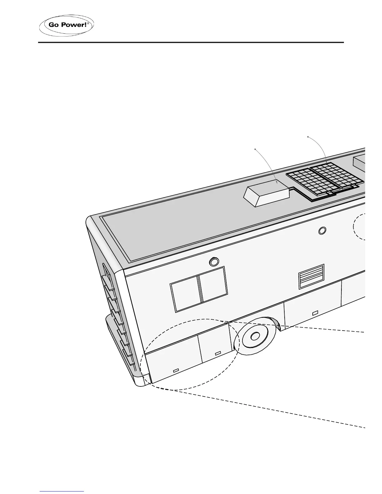
The following diagrams on pages 16-19 show how the GP-ISW-Inverter and GP-ISW-R are
typically installed in a mobile RV application. The diagrams show where the remote and Inverter
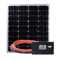
are installed and how the mobile power system can be integrated with a Go Power! RV Solar
Kit (sold separately by Go Power, please contact an authorized dealer directly).

Questions and Answers:

Question and Answer IconNeed help?

Do you have a question about the Go Power GP-ISW-1500 and is the answer not in the manual?

Go Power GP-ISW-1500 Specifications

General IconGeneral
BrandGo Power
ModelGP-ISW-1500
CategoryInverter
LanguageEnglish

Related product manuals