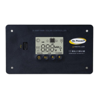
Solar Controller
GP-PWM-30
______________________________________________________________________
7
© 2012 Carmanah Technologies Corporation
September 2012
3.0 Tools and Materials Needed
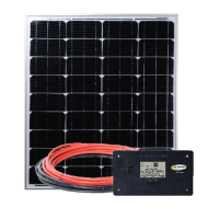
If the GP-PWM-30 Controller was purchased with a Go
Power! RV Solar Power Kit then UV resistant wire is
included. For instructions regarding the Go Power! RV
Solar Power Kit installation, please refer to the
Installation Guide provided with the Kit.
4.0 Choosing a Location
The GP-PWM-30 is designed to be mounted flush against a wall, out of
the way but easily visible.
The GP-PWM-30 should be:
mounted as close to the battery as possible.
mounted on a vertical surface to optimize cooling of the unit.
indoors, protected from the weather.
In a RV, the most common controller location is above the refrigerator.
The wire from the solar array most commonly enters the RV through the
fridge vent on the roof. PV connections should connect directly to the
controller. Positive and negative battery connections must connect
directly from the controller to the batteries. Use of a positive or negative
distribution bus is allowed between the controller and battery as long as
it is properly sized, electrically safe and an adequate wire size is
maintained.
 Loading...