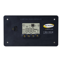
Solar Controller
GP-PWM-30
______________________________________________________________________
8
© 2012 Carmanah Technologies Corporation
September 2012
5.0 Installation Instructions
1. Prepare for mounting. Use the template provided at the end of
the manual to mark the four mounting holes and the “cutting line
for flush mounting.”
2. Complete the installation of the solar modules. If this GP-
PWM-30 was purchased as part of a Go Power! Solar Power Kit,
follow the Installation Guide provided. Otherwise, follow
manufacturer’s instructions for solar module mounting and
wiring.
3. Select wire type and gauge. If this GP-PWM-30 was
purchased as part of a Go Power! Solar Power Kit, appropriate
wire type, gauge, and length is provided. Please continue to
Section 6, “Operating Instructions.” If the GP-PWM-30 was
purchased separately, follow the instructions included here.
Wire type is recommended to be a stranded copper UV resistant wire.
Wire fatigue and the likelihood of a loose connection are greatly reduced
in stranded wire compared to solid wire. Wire gauge should be able to
sustain rated current as well as minimizing voltage drop.
Suggested Minimum Wire Gauge
(Cable length 25 ft max. from solar array to battery bank)
IMPORTANT: Identify the polarity (positive and negative) on the
cable used for the battery and solar module. Use colored wires or
mark the wire ends with tags. Although the GP-PWM-30 is
protected, a reverse polarity contact may damage the unit.
 Loading...