[page 26] | gpelectric.com
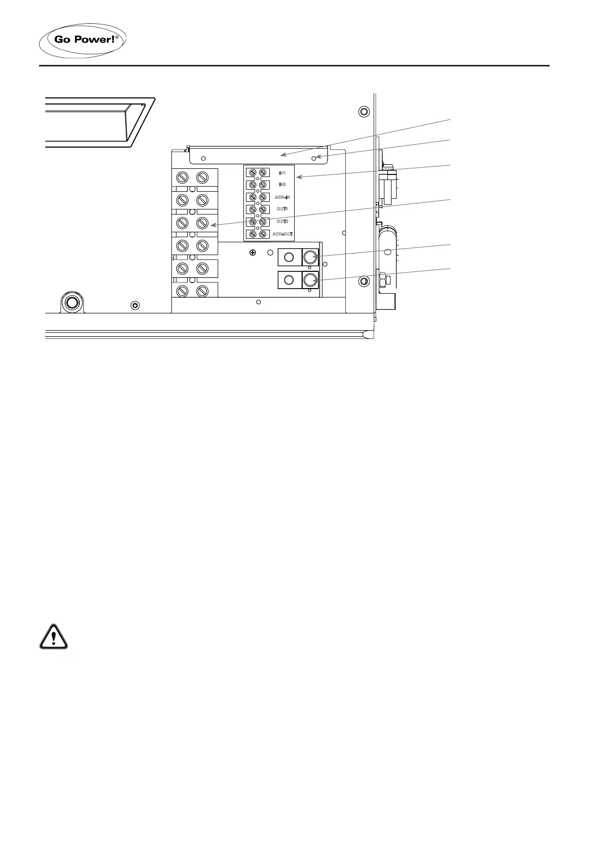
3.6.4 AC TERMINAL BLOCK CONNECTIONS
The IC Series has a six-pole AC terminal block and two AC ground terminals to connect the Inverter/Charger’s AC input and
output wiring.
The terminal block and ground terminals can be accessed by removing the three Phillips screws holding the AC cover plate.
Each connection on the AC terminal block is rated to accept one #14 to #6 AWG CU stranded wire, or two #12 AWG CU
strandedwires.Useaatheadscrewdrivertoreleaseandtightenthesetscrews.
TheACgroundterminalscanaccepttwo#14to#6AWGCUstrandedwire.Useaatheadscrewdrivertoreleaseandtighten
the set screws.
The IC Series’ ACN-IN and ACN-OUT terminals are electrically isolated from each other when in “inverting mode”, which
helps to prevent ground-loops. If the installation requires the AC Input and AC Output neutrals to be connected together, the
Inverter/Charger’s neutral-to-ground connection must be disconnected (See section 3.6.11).
3.6.5 AC CONDUCTOR WIRING
Make sure the IC Series is fully disconnected from the battery bank and no AC power is connected to the
Inverter/Charger before commencing any AC wiring connections.
Tighten terminal blocks on both sides periodically to correct torque specs.
ACINPUTSWIRING(50ADualIN,DualOutConguration)
• Remove the AC cover plate.
• Route the wires: IN1 (Hot1), IN2 (Hot2), ACN-IN (neutral), and Ground from the main panel through the AC Input
strain relief clamp. Tighten the strain relief clamp securely on the wires. Always leave a little extra slack in the wiring.
•
Connect the HOT1 wire (black) from the main panel to the Inverter/Chargers IN1 terminal. Connect the HOT2
wire (red) from the main panel to the Inverter/Charger’s IN2 terminal. Tighten the terminals securely, to 16 in lbf
(1.8 N-m). Note: To use the Battery Charger, IN1 must always be connected to an AC Input.
INSTALLATION
IN1
IN2
OUT1
OUT2
ACN-OUT
ACN-IN
IN1
IN2
OUT1
OUT2
ACN-OUT
ACN-IN
size : 55x36.5mm
Terminal label
Phillips screw boss x3
AC ground IN
(from main panel)
AC ground OUT
(to sub panel)
AC cover plate removed
AC terminal block
 Loading...