1/4
1/8
1/16
1/32
1/64
1/128
10
2
4
8
20
50
70
20-50
2
4
8
16
30
40
60-199
2
4
8
12
20
40
Hz
Wireless Flash Shooting: Optic Transmission
This product is compatible with Nikon Creative Lighting System
(CLS). It can function as either an optic wireless master or slave
flash. As a master unit, it can control Nikon speedlights e.g. SB-
900 and SB-910 via wireless. As a slave unit, it can be controlled
by wireless signals of Nikon speedlights e.g. SB-900 and pop-up
flash commanders of Nikon cameras e.g. D7100/D7000/D800.
- 39 - - 40 -
Maximum Stroboscopic Flashes:
1/4
1/8
1/16
1/32
1/64
1/128
1
7
14
30
60
90
90
2
6
14
30
60
90
90
3
5
12
30
60
90
90
4
4
10
20
50
80
90
5
4
8
20
50
80
90
6-7
3
6
20
40
70
90
8-9
3
5
10
30
60
80
Flash
output
Hz
Flash
output
● You can set up three slave groups for i-TTL autoflash shooting.
With i-TTL autoflash, you can easily create various lighting effects.
● Any flash settings for the slave units on the master flash in i-TTL /
Manual / RPT mode will be automatically sent to the slave units.
So the only thing you need to do is to set the master unit for each
slave group without any operation for the slave units at all during
the shooting.
● This flash can work in i-TTL / M / RPT / OFF flash modes when set
as a master unit.
Slave/Master Unit's Positioning and Operation Range
Slave Unit Setting
Master Unit Setting
● Even with multiple slave units, the master unit can control
all of them via wireless.
● In this user manual, “master unit” refers to the camera flash
on a camera and “slave unit” will be controlled by the
master unit.
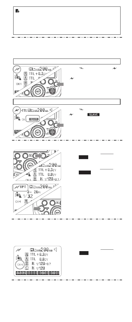
1. Wireless Settings
You can switch between normal flash and wireless flash. For normal
flash shooting, be sure to set the wireless setting to OFF.
Indoors
Outdoors
15m(49.2ft)
10m(32.8ft)
80°
8m(26.2ft) 12m(39.4ft)
Press < > button so that < >
is displayed on the LCD panel. If
< RPT> is displayed, it means
RPT mode is ON.
The backlight turns green now.
Press < > button again so that
< > and < > are
displayed on the LCD panel.
The backlight turns orange now.
2. Setting Master Unit's Flash Mode
Press Function Button 4
1 < > to choose the
group from M/A/B/C. Then,
press Function Button 3
< > so that the
master unit can work in OFF
/ i-TTL / M flash mode.
Choose one of them as the
flash mode of master unit.
Press the “MODE/Lock
2 “button can change to RPT
mode.
Gr
MODE
3. Setting the Communication Channel
If there are other wireless flash systems nearby, you can change the
channel IDs to prevent signal interference. The channel IDs of the
master unit and the slave unit(s) must be set to the same.
Press Function Button 3
1 < > and turn the
Select Dial to choose a
channel ID from 1 to 4.
Press the <SET> button to
2 confirm.
CH
4. Wireless ID Settings
Change the wireless channels and wireless ID to avoid interference
for it can only be triggered after the wireless IDs and channels of the
master unit and the slave unit are set to the same.
Press the <MENU> button to enter C.Fn ID. Press the <SET> button
to choose OFF channel expansion shutdown, and choose any figure
from 01 to 99.
 Loading...