FA-Plus/C
SEC
PRI
~~
+ +
--
SEC
PRI
~~
+ +
--
32
33
CV+CV- D
Malla
Vin-AinAout Vin+ Vout-Vout++
CN1 CN2
-
CV+CV- D
Malla
Vin-AinAout Vin+ Vout-Vout++
CN1 CN2
-
JP
4321
JP
4321
A
A
_
_
+
+
D
D
Malla
Malla
V
in
V
in
V
out
V
out
CN4
CN4
A
_
+
D
Malla
V
in
V
out
CN4
A
_
+
D
Malla
V
in
V
out
CN4
E
E
D1
D1
D2
D2
+
+
D4L-PLUS
D4L-PLUS
JP1
JP1
S
S
1
4
7
2
5
8
3
6 0
9
C
1
4
7
2
5
8
3
6 0
9
C
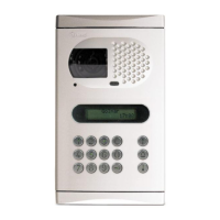
FA-Plus/C or FA-Plus
Main Main
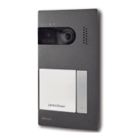
Slave door panelMaster door panel
*Place this power supply
as closest as possible
to the first distributor.
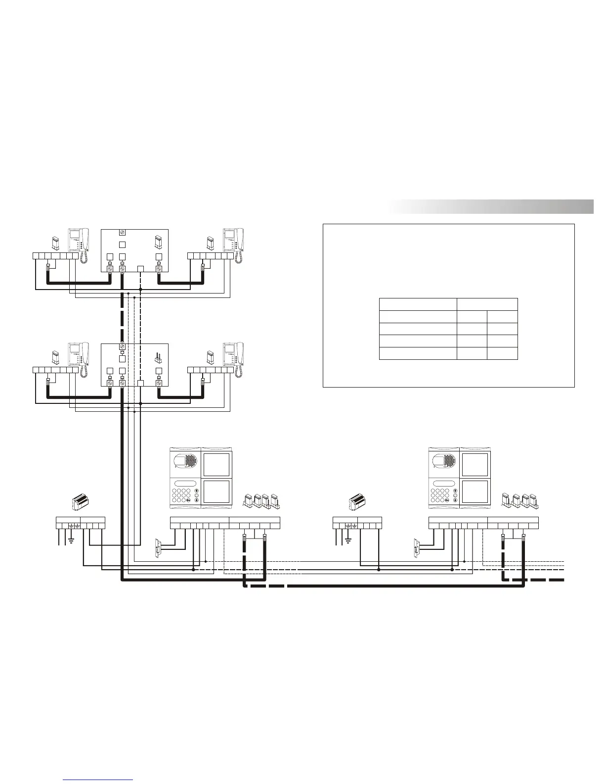
INSTALLATION DIAGRAMS
ideo installation with coaxial cable.
v
The installation diagram shows the connection of a video system with one or several door
panels for the same building.
If the system has one door panel only, override the wiring to the second door panel.
If the system has more than one door panel, wire the second panel as shown on the
diagram. In case of more than two door panels, wire them as the second is connected.
1,00mm² 2,50mm²
0,25mm² 0,25mm²
RG-59 RG-59
Terminal
SECTIONS CHART
50m.
Distance
150m.
A , A , A, D
in out
V , V , V , V
in+ out+ in out
+, –, CV+, CV–
For longer distances than the specified contact with your distributor.
* Take off JP1 jumper
of all the distributors
except in the last one.