103
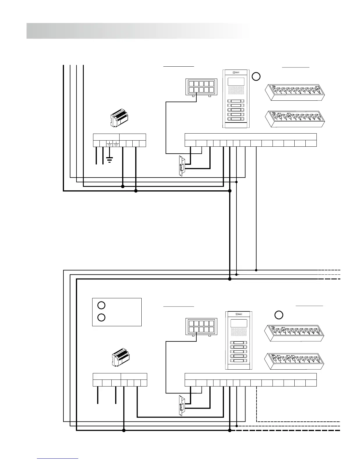
INSTALLATION DIAGRAMS
FA-Plus o FA-Plus/C
SEC
PRI
~~
+ +
--
FA-Plus/C
SEC
PRI
230
--
110 0
+ +
S
D
Malla
Vin-AinAout Vin+ Vout-Vout+
CN1
+
-
+CV1CV2
-
D
Malla
Vin-AinAout Vin+ Vout-Vout+
CN1
+
-
+CV1CV2
-
To telephones
Main
Main
General door panel
Inner door panelBACKBONE 1
EL501 mode
EL500 mode
BACKBONE 0
M =Master.
S =Slave.
10
1
9
2
8
3
7
4
6
5
CN3
10
1
9
2
8
3
7
4
6
5
CN3
M
Lock release
Vd.c.
Lock release
Vd.c.
SW2
SW1
SW1
SW2
104
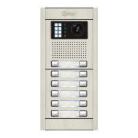
GENERAL DOOR PANEL
SEC
PRI
~~
+ +
--
FA-Plus o FA-Plus/C
D
Malla
Vin-AinAout Vin+ Vout-Vout+
CN1
+
-
+CV1CV2
-
To telephones
A
udio installation with general door panel
to large residential complexes.
1,50mm² 2,50mm²
0,25mm² 0,25mm²
Terminal
SECTIONS CHART
100m.
Distance
300m.
A , A , A, D
in out
For greater distances contact our technical support department.
+, , CV1, CV2–
Main
IMPORTANT NOTES:
To install and configure properly, do always follow the enclosed information.
The installation diagram shows the connection of an audio system with one general door panel
and up to 120 inner door panels (backbones/buildings).
In case of more than one general door panel, wire them as it shows in the video installation
diagram, (see page 99).
BACKBONE 120
Inner door panel
EL500 mode
10
1
9
2
8
3
7
4
6
5
CN3
M
Lock release
Vd.c.
SW1
SW2