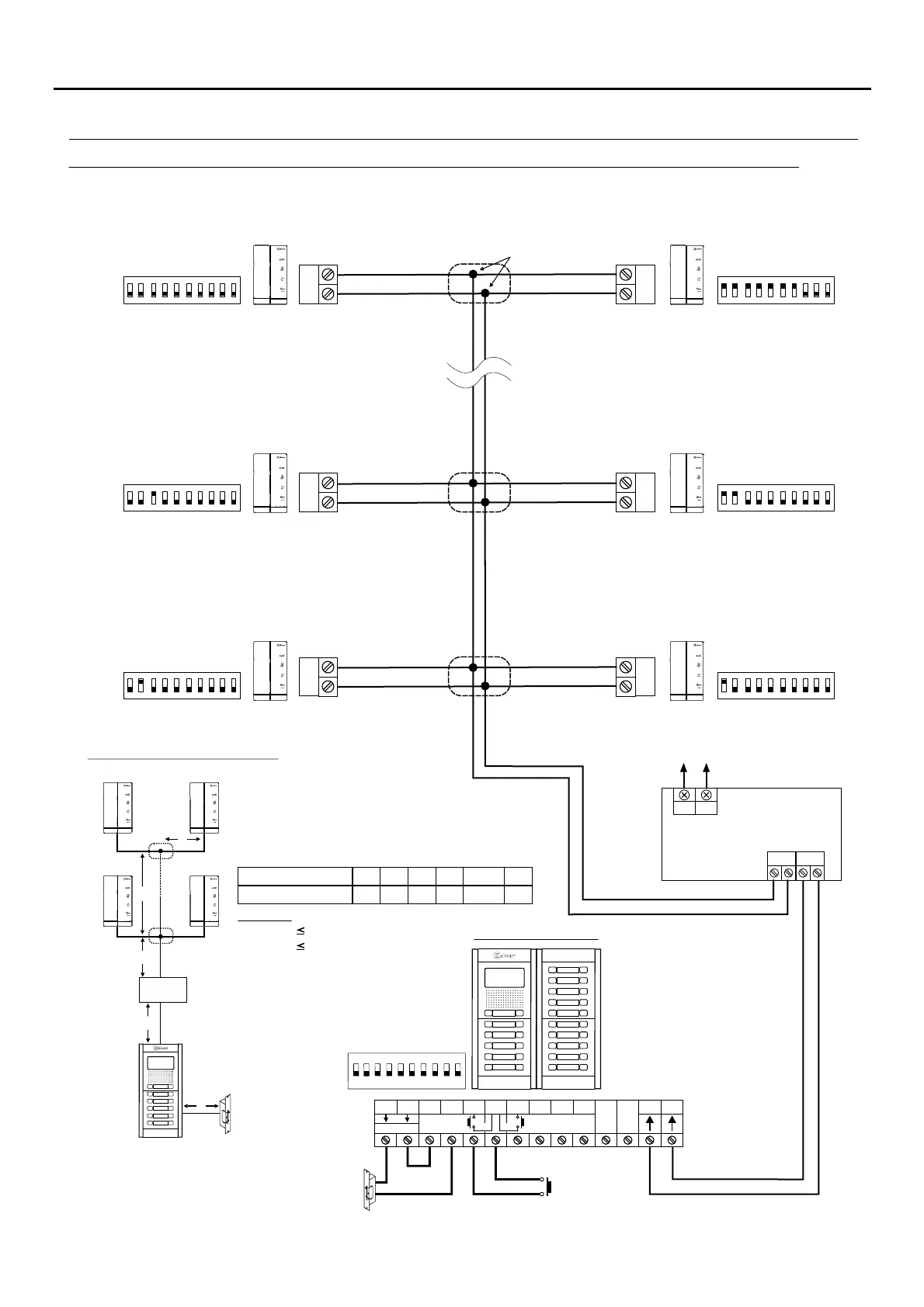
WIRING DIAGRAMS:
13
For more information about the door panel, installation, configuration, connection of an AC lock release, 2nd lock release mixed installation,
and other wiring diagrams ( )with monitors and telephones , see the corresponding door panel manual .T-ART/G2+
Audio door entry system with 128 apartments / T-ART-G2+ telephones Golmar .and d.c lock release
Only audio installation, configure
the end of line ni
Dip 10 OFFto all
telephones.
AP
(1)
(1)
*
( )
NA2
+
AP-
C1
NA1
AP+
C2
AP+
GND
BUSBUS
Relé 2Relé 1
_
12Vdc
NC2
CCTV
Distances and cross-sections:
Mains
100~240Vac
BUS (M) BUS(PL)
FA-G2+
LN
Access door panel
1 2 3 4 5 6 7 8 910
ON
T-ART/G2+
APARTMENT 2
ON
1 2 3 4 5 6 7
8 9 10
BUS
BUS
BUS
*
( )
T-ART/G2+
APARTMENT 4
ON
1 2 3 4 5 6 7
8 9 10
*
( )
T-ART/G2+
Master
APARTMENT 128
ON
1 2 3 4 5 6 7
8 9 10
*
( )
A
E
C
FA- 2+G
D
B
A B
80m 20m
Cable
C
96m
RAP-GTWIN/HF 2x1mm
2
D
15m
B+C+D
130m
E
15m
T-ART/G2+
APARTMENT 1
ON
1 2 3 4 5 6 7
8 9 10
BUS
BUS
BUS
T-ART/G2+
APARTMENT 3
ON
1 2 3 4 5 6 7
8 9 10
T-ART/G2+
APARTMENT 127
ON
1 2 3 4 5 6 7
8 9 10
Make the connections in
electrical junction box.
B: must be to 20m.
D: must be to 15m.
Important:
*
( )
*
( )
*
( )
Master
Master
Master
Master Master
Lock release
a dm x. 12 V c/270mA.
1
( )
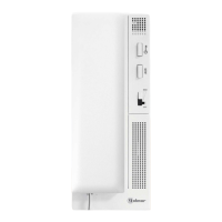
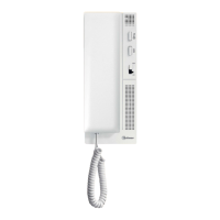
T-ART/G2+ TELEPHONE
T-ART
AUX
T-ART
AUX
T-ART
AUX
T-ART
AUX
AUX AUX
AUX AUX
AUX AUX