INSTALLATION DIAGRAMS
Installation for 32 apartments/T562 GB2 telephones and Golmar D.C. lock release:
8
Access panel
NA2
+
AP-
C1
NA1
AP+
C2
AP+ AP-
P1 P2
BUSBUS
Relay 2
Relay 1
_
12Vdc
Lock release
max. 12 Vdc/270mA.
ON
1 2 3 4 5 6
AP
SW1
CODE 0
Twisted pair 2x0.75mm
Twisted pair 2x1mm
60m
A
60m
B
80m 80m
Cable
2
2
10m
C
15m
IMPORTANT: Configure the
dip switch as shown in the
diagram.
*
( )
*
( )
Distances and Cross-Sections:
L1
L2
T-562 GB2
Master
CODE 1
L1
L2
T-562 GB2
Master
CODE 31
L1
L2
T-562 GB2
Master
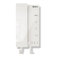
T562 G 2B TELEPHONE
APARTMENT 1
APARTMENT 2
APARTMENT 32
*
( )
*
( )
For further information about the door panel, AC lock release connection a second lock release mixed installations with monitors and audio terminals,, or
( u msee the “T632/GB2 ser anual (code 50121878)”.
https://doc.golmar.es/search/manual/50121878
T562
A
C
B
T562
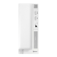
FA- 2GB /A
Mains
100~240Vac
N L
CN
BUS (M) BUS (PL)
FA- 2GB /A
L
*
( )
*
( )
*
( )
 Loading...