MONITOR DESCRIPTION
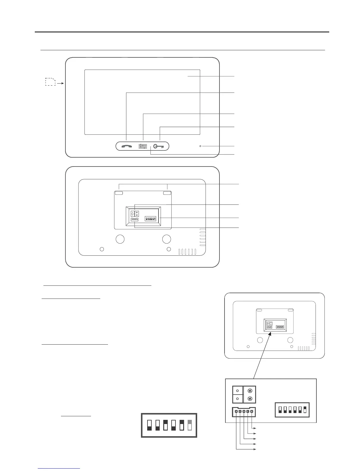
Installation terminals and dip switch:
( ):WHITE HZ+
( ):GREEN HZ-
Connection terminals:
L1, L2: .BUS Connection
HZ+, HZ-: Door bell push button connection.
CALL REPEATER, GND: , (SAR-12/24).Call repeater connection
(12Vcc/50mA ).maximum
Configuration dip switch:
Dip6: Sets the end of line. Set to ON in monitors where the bus cable
terminates. Set to OFF only in intermediate monitors.
Dip1 a Dip5: .Set the monitor address (addresses 0 to 31)
Switches set to OFF have a value of zero.
The values of the switches set to ON are shown in the enclosed chart.
The monitor code will be the sum of the values of the switches set to
ON.
1 2 3
ON DIP
4 5 6
L1
L2
( ):RED CALL REPEATER
( ):BLACK GND
( ):YELLOW D NOT USEO
4
1 2 3
ON DIP
4 5 6
E : 0 + 0+4+0+16 = 20xample
Switch number: 1 2 3 4 5
ON : 1 2 4 8 16value
Value chart
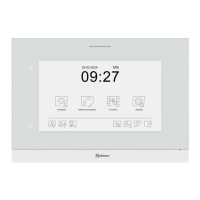
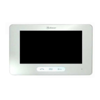
THERA G 2B MONITOR
1 2 3
ON DIP
4 5 6
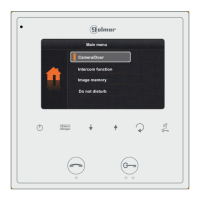
7” TFT colour screen.
Start/stop communication push button.
:During standby Display the door panel
.image
Microphone.
Micro SD
Card
Attachment holes.
BUS connection terminals.
Con#guration DIP switch.
Con ector.n
1 2 3
ON DIP
4 5 6
Menu access button.
Door release push button.
Monitor status light.
 Loading...