.
P
ush buttons wiring
DOOR PANEL INSTALLATION
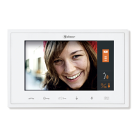
For a quality finish, pass the push buttons wires through
the spacer hole of the closest module It's
recommended to use wires with sections
2
0.25mm section
.
between 0,1 and .
IMPORTANT:
.
.
(if there is).
link the push buttons common
terminal of the several push buttons modules
The common terminal of the push buttons
contained in a module are linked from factory
This wire must be connected to the CP terminal
of the EL500/V2PLUS microprocessor module
and to the corresponding CP terminal of its
EL516 encoder circuit
T.
circuit
.
wist the call wires as shown The call wires will be
connected to the EL500/V2PLUS microprocessor
or to the corresponding EL516 push buttons
encoder
.
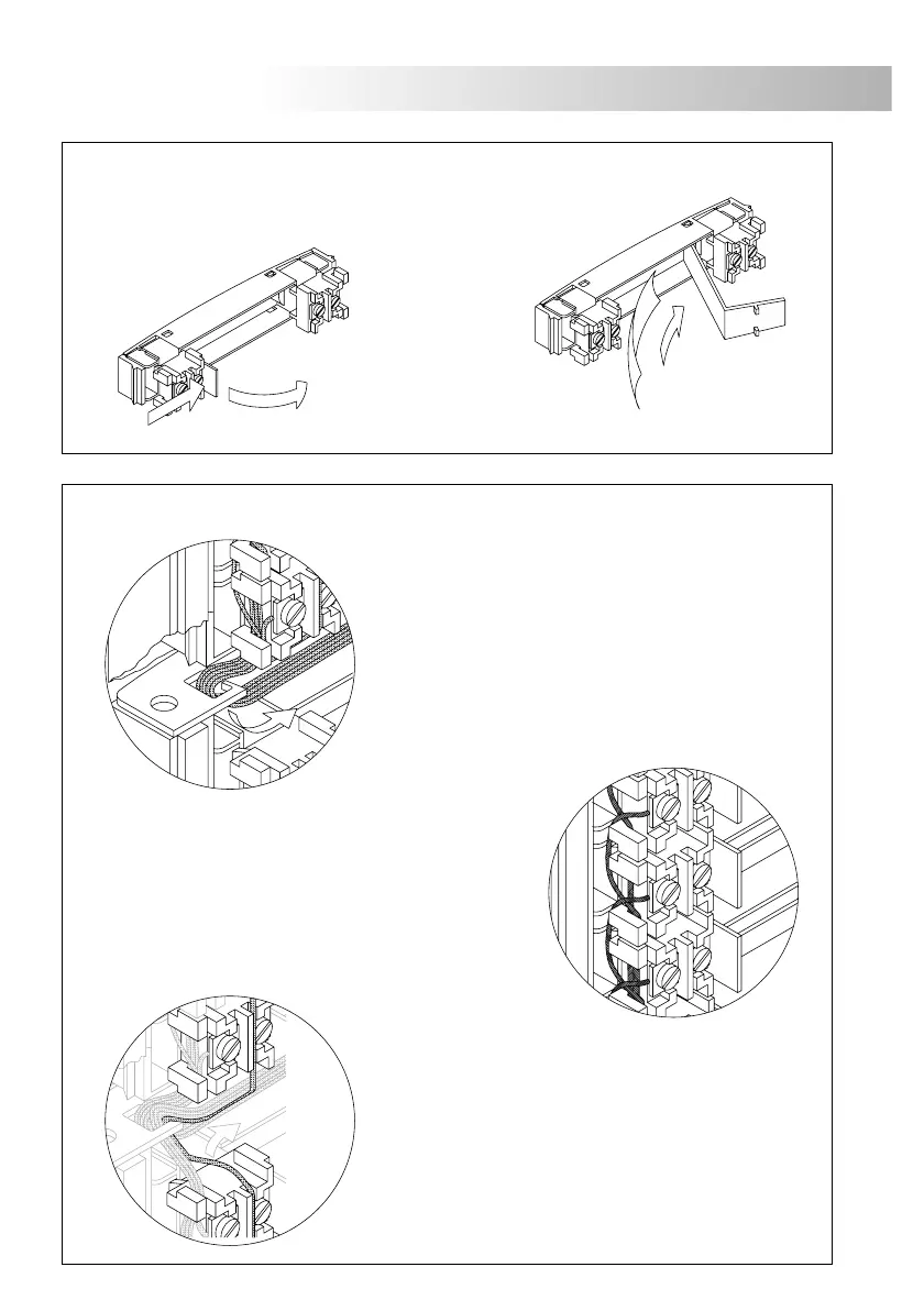
P
lace the nameplate labels
Open the label holder.
Place the label
and close .
DOOR PANEL INSTALLATION
.
H
old the door panel on the embedding box
Select a direction to open the door panel; this selection should
eas the door panel wiring
The opening direction will be settled through the hinges position,
that must be passed through the header clips as shown For
example, if the hinges are placed on both clips of the lower
header, the door panel will open downwards; if they are placed
on the right clips of both headers, the door panel will open
to left
e .
.
.
To hold the door panel on the embedding
box, insert the hinges in the embedding
box lockers as shown
.
Link the sound module with the EL500/V2PLUS
microprocessor circuit by using the supplied
flat cable
.
79
80