Do you have a question about the Goodman CH SERIES and is the answer not in the manual?
Disconnect all power before servicing. Multiple power sources may be present to avoid injury or death.
Installation by individuals meeting AHRI 'Entry Level Technician' requirements is mandatory to prevent damage or injury.
Inspect product for shipping damage and verify model/specs. Carrier is responsible for transportation damage claims.
Installer responsible for compliance with national/local codes and EPA refrigerant regulations to avoid fines.
Provide complete product model and serial numbers for ordering replacement parts through contractor/distributor.
Steps for attaching duct flanges, including removing shipping bracket and securing bottom flange with screws.
Mandatory auxiliary drain pan for coils above ceilings to prevent overflow damage; termination must be visible.
Primary/secondary drain connections, torque limits (37 in-lbs), pipe types (PVC/metal), and insertion depth.
Pitch drain lines 1/4" per foot for drainage, insulate to prevent sweating, and install a primary condensate trap.
Use quenching cloth, 5% silver alloy brazing, and ensure clean, round ends to prevent leaks and finish damage.
Apply heat proportional to tube size, use heat shields to avoid burning serial plates or unit finish.
Coil is shipped under pressure. Follow instructions carefully to prevent injury during handling and installation.
Steps to loosen nut, remove cap, check piston, braze tailpiece, and torque nut for flowrator adjustment.
Excessive torque can cause orifices to stick; use proper torque settings when tightening orifices.
Important note that Piston Kit Chart (PKC-XX) instructions do not apply to CH coils; piston kits are purchased separately.
Lists approved chemical cleaners for aluminum coils; flush with water or use listed products, rinse well after use.
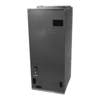
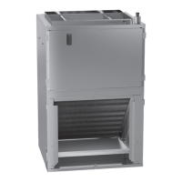
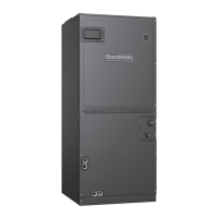
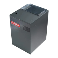
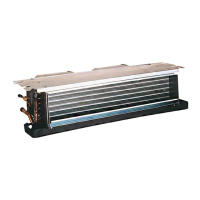
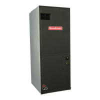
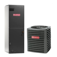
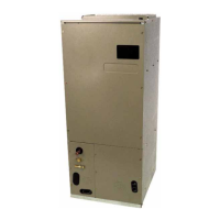
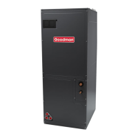
This document provides installation instructions for a horizontal two-way coil, which is a component used in HVAC systems, specifically with furnaces and air handlers. Its primary function is to facilitate heat exchange as part of a refrigeration cycle, typically for cooling. The "two-way" designation indicates its versatility in installation, allowing it to be configured for either right or left-hand applications without requiring internal conversion. This adaptability simplifies installation in various setups, as the coil can be oriented based on the best access for refrigerant lines and condensate drainage.
The coil is designed to be installed upstream (discharge air side) of a furnace or downstream (return air side) of an air handler. This placement is crucial for its proper operation within the HVAC system, ensuring that the air flows through the coil correctly for effective heat transfer. The installation process involves attaching the coil to the furnace and then connecting the plenum to the coil. For situations where the coil and furnace dimensions (depth and width) are not identical, a field-supplied transition piece can be used to center the openings, ensuring a tight and efficient connection. Additionally, a Z-bracket attachment is provided to secure the coil to a narrower furnace, accommodating different equipment sizes and maintaining structural integrity.
A key feature of this coil is its condensate management system. It includes both a primary and an optional secondary drain with 3/4" NPT female connections. This dual-drain system is vital for preventing water overflow and potential damage, especially when the coil is installed above ceilings or in other locations where water discharge could cause issues. The document emphasizes the mandatory installation of a field-fabricated auxiliary drain pan in such scenarios, with drain lines terminated visibly to alert the homeowner of any primary drain blockages. Proper pitching of the drain lines (1/4" per foot) is required to ensure free drainage, and insulation of the lines inside the building is recommended to prevent sweating and dripping. The instructions also detail the importance of installing a condensate trap in the primary drain line to ensure proper drainage and prevent air from being drawn back through the drain during fan operation, which could hinder condensate removal or allow conditioned air to escape. Different trap designs, such as a running trap, are discussed, with specific dimensions (1" or 2" minimum depth) to ensure unrestricted condensate flow.
Maintenance features primarily revolve around the refrigerant lines and coil cleaning. The coil is shipped under pressure, and specific instructions are provided for safely handling the refrigerant lines during installation, including loosening nuts to release tracer gas and using a tube cutter to prepare the lines. Brazing of the refrigerant lines requires careful attention to detail, including using a quenching cloth to protect painted surfaces, ensuring clean and burr-free cut ends, and using brazing alloy with a minimum of 5% silver content. The document cautions against applying excessive heat to avoid melting the tubes and recommends using a heat shield to protect the unit's finish or serial plate. After installation, checking for leaks and proper charging of the system are essential steps.
For cleaning the aluminum tube evaporator coil, the recommended method is to simply flush it with water. However, an alternate method using approved chemical cleaners is also provided, with a list of specific products deemed safe for use with round tube aluminum coils. The document stresses the importance of thoroughly rinsing the coils after using any chemical cleaners to prevent residue buildup.
Another important aspect is the flowrator distributor assembly, which manages refrigerant flow. The coil comes with a check-style flowrator, and while no change is typically needed for matching applications, mix-matched setups may require a different piston size. The instructions detail the procedure for changing the piston, including safely releasing pressure, removing the old piston, and installing the correct one. Proper torque settings for tightening the 13/16 nut are emphasized to prevent orifices from sticking.
Overall, the device is designed for reliable and efficient operation within an HVAC system, with features that prioritize flexible installation, effective condensate management, and straightforward maintenance procedures, all while adhering to safety and environmental regulations.
| Series | CH |
|---|---|
| Cooling Capacity | 18, 000 to 60, 000 BTU/H |
| Airflow | Up to 2000 CFM |
| Motor Type | ECM |
| Voltage | 208/230V |
| Stages | Single Stage |
| Cabinet | Galvanized Steel |
| Refrigerant | R-410A |
| Sound Level | Varies by Model |
| Warranty | 10-Year Limited Parts Warranty |