This document is a technical manual for Goodman CKF 50 Hz Condensing Units, providing comprehensive information for qualified HVAC technicians regarding installation, operation, troubleshooting, and maintenance.
Function Description
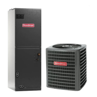
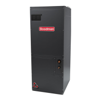
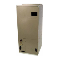
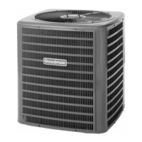
The Goodman CKF 50 Hz Condensing Units are designed for use in split-system air conditioning applications. These units are responsible for rejecting heat from the refrigerant cycle to the outdoor air, thereby cooling the indoor space. They are available in various ton sizes, ranging from 1.5 to 10 tons, and are designed for 220/240 to 380 volt single-phase or three-phase applications, depending on the model. The condenser air is pulled through the condenser coil by a direct-drive propeller fan and discharged out of the top of the cabinet. These units are designed for free air discharge, meaning no additional resistance from ductwork should be attached.
The manual emphasizes that installation and repair should be performed only by individuals meeting the requirements of an "entry-level technician" as specified by the Air-Conditioning, Heating, and Refrigeration Institute (AHRI) to prevent product damage, personal injury, or death. Goodman disclaims responsibility for property damage or personal injury resulting from improper service or unqualified personnel.
Important Technical Specifications
The model numbers follow a specific identification system:
- Category: C (Split Systems)
- Product Family: K (Air Conditioner)
- Nominal Capacity: Ranges from 018 (1.5 Tons) to 120 (10 Tons).
- Electrical:
- 1: 208-230V/1 phase/60Hz
- 2: 220-240V/1 phase/50Hz
- 3: 208-230V/3 phase/60Hz
- 5: 308-415V/3 phase/50Hz
- Refrigerant: CKF**-P models are shipped without refrigerant but are pressurized with a nitrogen holding charge. This charge must be removed, and the unit evacuated and charged as per installation instructions.
- Compressors: CKF condensing units utilize a mix of Copeland Reciprocating® and Copeland Compliant® Scroll compressors. Scroll compressors are noted for being more tolerant of liquid refrigerant and feature an internal equalization mechanism and an anti-counter rotation device.
- Refrigerant Charge: Factory installed for the matching evaporator coil and a 15-foot [5 m] refrigerant line set.
- Liquid Line O.D.: 3/8 inch [9.6 mm] for all models.
- Suction Line O.D.: 3/4 inch [19.1 mm] for 1.5-2 ton models, 7/8 inch [22.3 mm] for 3-10 ton models.
- Electrical Conduit Size: 1/2 or 3/4 inch [13 or 20 mm].
- Minimum Circuit Ampacity (MCA) and Maximum Overcurrent Device (MOCD): Vary by model, e.g., CKF24-2* has an MCA of 16.6 and MOCD of 25, while CKF70-5* has an MCA of 14.8 and MOCD of 20.
- Dimensions (W x D x H):
- CKF24-2*, CKF36-2*, CKF36-5*: 26" [660] x 26" [660] x 29¾" [756]
- CKF48-5*: 29" [737] x 29" [737] x 29¾" [756]
- CKF60-5*: 29" [737] x 29" [737] x 32¼" [819]
- CKF70-5*: 29" [737] x 29" [737] x 38¼" [972]
- Approximate Shipping Weight: Ranges from 180 lbs [82 kg] for CKF24-2* to 228 lbs [104 kg] for CKF70-5*.
The manual includes detailed "Expanded Performance Data" tables for various models (CKF24-2*, CKF36-2*, CKF36-5*, CKF48-5*, CKF60-5*, CKF70-5*). These tables provide cooling operation data across different outdoor ambient temperatures (75°F, 85°F, 95°F, 105°F, 115°F) and entering indoor wet bulb temperatures (58°F, 63°F, 67°F, 71°F). Data points include MBH (cooling capacity), sensible heat, latent heat, EER (Energy Efficiency Ratio), AMPs (current draw), and CFM (airflow).
Usage Features
- Installation: The suction and liquid line connections are of the sweat type for field piping with refrigerant-type copper. Back-seating valves are factory-installed.
- Clearances: Proper placement is crucial for air circulation. The top of the unit should ideally be completely unobstructed. If placed beneath an obstruction, a minimum of 60 inches [152 cm] clearance is required between the top of the unit and the obstruction(s). Corner installations are strongly discouraged.
- Location Restrictions: Do not locate the unit directly under a gas appliance vent termination, within 3 feet [1m] of a clothes dryer vent, where refreezing of defrost water would create a hazard, or where water may rise into the unit.
- System Sizing: Systems should be properly sized based on heat gain and loss calculations according to methods from the Air Conditioning Contractors Association (ACCA) or equivalent.
- Performance Test: A properly operating unit should fall within specific tolerances:
- Subcooling: ±2 degrees of the value shown in installation instructions.
- Delta T (indoor air temperature drop): ±3 degrees of the typical value.
- HI PR (high side pressure): ±10 PSIG of the value shown.
- LO PR (low side pressure): ±5 PSIG of the value shown.
- Amps: ±3 Amps of the typical value.
Maintenance Features
- Safety: Disconnect ALL power before servicing or installing the unit. Multiple power sources may be present. Failure to do so may cause property damage, personal injury, or death.
- Refrigerant Handling: The United States Environmental Protection Agency ("EPA") has regulations regarding the introduction and disposal of refrigerants. Failure to follow these regulations can harm the environment and lead to substantial fines.
- Approved Devices: Do not connect or use any device not design-certified by Goodman for use with this unit to prevent property damage, personal injury, reduced unit performance, and/or hazardous conditions.
- Flammable Materials: Do not store combustible materials or use gasoline or other flammable liquids or vapors in the vicinity of this appliance.
- Wiring: Wiring diagrams are provided for CKF[24-36]M/N/P and CKF[48-70]M/N/P models, showing component codes and color codes. The manual states that wiring is subject to change and technicians should always refer to the most up-to-date wiring diagram on the unit. All electrical connections must comply with national and local electrical codes, using copper wire only.
- Oil Compatibility: Copeland Compliant® Scroll compressors use white oil compatible with 3GS oil. 3GS oil may be used if additional oil is required.
- Troubleshooting: Refer to Service Manual RS6100004 for installation, operation, and troubleshooting information. All safety information must be followed as provided in the Service Manual.
- Parts Information: Refer to the appropriate Parts Catalog for part number information.