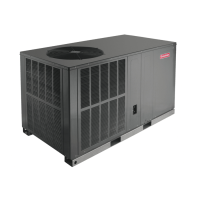
11
E
V
A
P
O
R
A
T
O
R
COOLING
SERVICE VALVE
SERVICE PORT
REVERSING VALVE
C
O
N
D
E
N
S
E
R
SERVICE PORT
COMPRESSOR
SERVICE PORT
ACCUMULATOR
EXPANSION DEVICE
CHECK VALVE
ORIFICE
SERVICE
VALVE
CHECK VALVE
ORIFICE
INDOOR
COIL
DISTRIBUTOR
OUTDOOR
COIL
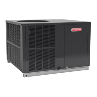
E
V
A
P
O
R
A
T
O
R
HEATING
SERVICE VALVE
SERVICE PORT
REVERSING VALVE
C
O
N
D
E
N
S
E
R
COMPRESSOR
SERVICE PORT
ACCUMULATOR
CHECK VALVE
ORIFICE
SERVICE
VALVE
CHECK VALVE
ORIFICE
INDOOR
COIL
DISTRIBUTOR
OUTDOOR
COIL
DISTRIBUTOR
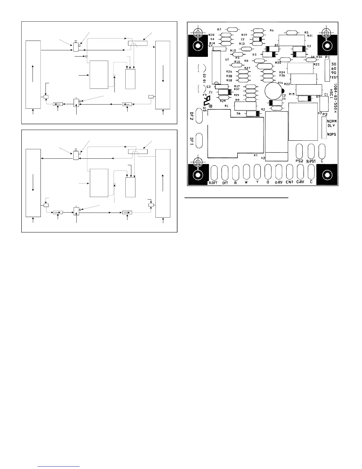
DEFROST C ONTROL
During operation the power to the circuit board is controlled
by a temperature sensor, which is clamped to a feeder tube
entering the outdoor coil. Defrost timing periods of 30, 60 and
90 minutes may be selected by setting the circuit board jumper
to 30, 60 and 90 respectively. Accumulation of time for the
timing period selected starts when the sensor closes
(approximately 34°F), and when the wall thermostat calls for
heat. At the end of the timing period, the unit’s defrost cycle
will be initiated provided the sensor remains closed. When
the sensor opens (approximately 60°F), the defrost cycle is
terminated and the timing period is reset. If the defrost cycle
is not terminated due to the sensor temperature, a twelve
minute override interrupts the unit’s defrost period.
Suggested Field Testing/Trouble Shooting
1. Run unit in the heating mode (room thermostat calling for
heat).
2. Check unit for proper charge. NOTE: Bands of frost on the
condenser coil indicate low refrigerant charge.
3. Shut off power to unit.
4. Disconnect outdoor fan by removing the outdoor fan motor
wire from “DF2” on defrost control.
5. Restart unit and allow frost to accumulate.
6. After a few minutes of operation, the unit’s defrost
thermostat should close. To verify this, check for 24 volts
between “DFT” and “C” on board. If the temperature at the
thermostat is less than 28°F and the thermostat is open,
replace the unit’s defrost thermostat, as it is defective.
7. When the unit’s defrost thermostat has closed, short the
test pins on the defrost board until the reversing valve
shifts, indicating defrost. This should take up to 21
seconds depending on what timing period the control is
set on. After defrost initiation, the short must instantly be
removed or the unit’s defrost period will only last 2.3
seconds.
8. The control is shipped from the factory with the compressor
delay option selected. This will de-energize the
compressor contactor for 30 seconds on defrost initiation
and defrost termination. If the jumper is set to Normal, the
compressor will continue to run during defrost initiation
and defrost termination. The control will also ignore the
low pressure switch connected to R-PS1 and PS2 for 5
minutes upon defrost initiation and 5 minutes after defrost
termination.
9. After the unit’s defrost thermostat has terminated, check
the defrost thermostat for 24 volts between “DFT” and “C”.
The reading should indicate 0 volts (open sensor).
10. Shut off power to unit.
11. Replace outdoor fan motor lead to terminal “DF2” on defrost
board and turn on power.