12
AIR FLOW M EASUREMENT AND A DJUSTMENT
Please review the Duct Work section before proceeding
with the airflow measurements and adjustments in this
section.
Unit blower curves (see Specification Sheets) are based on
external static pressure (ESP per in/W.C.). The duct openings
on the unit are considered internal static pressure. As long as
ESP is maintained, the unit will deliver the proper air up to the
maximum static pressure listed for the CFM required by the
application (i.e. home, building, etc.)
In general, 400 CFM per ton of cooling capacity is a rule of
thumb. Some applications depending on the sensible and
latent capacity requirements may need only 350 CFM or up to
425 CFM per ton. Check condition space load requirements
(from load calculations) and equipment expanded ratings data
to match CFM and capacity.
After unit is set and duct work completed, verify the ESP with a
1-inch inclined manometer with pilot tubes or a Magnahelic
gauge and confirm CFM to blower curves in the Specification
Sheets.
NOTE: Never run CFM below 350 CFM per ton, evaporator
freezing or poor unit performance is possible.
AIR F LOW ADJUSTMENTS FOR INDOOR B LOWER MOTOR
X-13 Motor
Adjust the CFM by changing the 24V low voltage lead at the
speed terminal block on the motor. (T1-Low Speed, T2 and
T3-Medium Speed, T4 and T5-High Speed).
NOTE: Factory set T1 (G, fan), T2 (cool/Hi cool), T3 (W2 electric
heat), T4 and T5 reserved for high static (cool/Hi cool) and
W2. GPH1548M41 and GPH1560M41 low cool Y1 will run at G
speed.
ECM Motor
The ECM control board is factory set with the dip switch #4 in
the “ON” position for single stage units and to the "OFF"
position for the 2 stage units. All other dip switches are factory
set in the “OFF” position. For most applications, the settings
are to be changed according to the electric heat size.
The ECM motor provides many features not available on the
traditional PSC motor. These features include:
• Improved Efficiency
• Constant CFM
• Soft Start and Stop
• Improved Humidity Control
ECM Motor Speed Adjustment
Each ECM blower motor has been preprogrammed for
operation at 4 distinct air flow levels when operating in Cooling/
Heat Pump mode or Electric Heat mode. These 4 distinct
levels may also be adjusted slightly lower or higher if desired.
The adjustment between levels and the trim adjustments are
made by changing the dip switch(s) either to an "OFF" or "ON"
position.
See Appendix for Blower Performance Data tables.
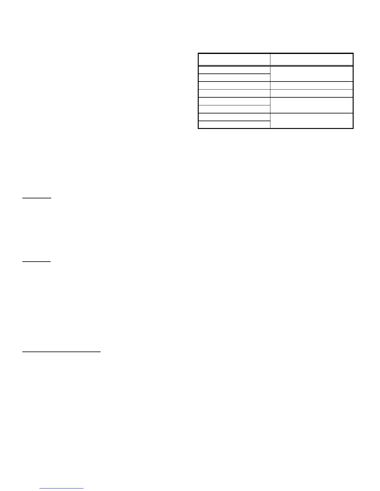
APH DIP SWITCH FUNCTIONS
The ECM motor has an electronic control that contains eight
(8) 2-position dip switches. The function of these dip switches
is shown in Table 1.
DIP SWITCH NUMBER FUNCTION
1
2
3N/A
4 Indoor Thermostat
5
6
7
8
Cooling & Heat Pump CFM
CFM Trim Adjust
Electric Heat
Table 1
For APH1524-43 models, dip switch 4 must be set to ON. Dip
switch 4 must be set to OFF for two-stage compressor models
APH1549-60. Dip switch 4 ON energizes Y1 signal to the
ECM motor anytime Y/Y2 is energized. The indoor motor will
not operate properly if switch is not set correctly for the model.
APH CFM DELIVERY AND ADJUSTMENTS
See Appendix for CFM Output, Adjustments and DIP switch
settings.
APH THERMOSTAT “FAN ONLY” MODE
During Fan Only Operations, the CFM output is 50% of the high
stage cooling setting.
APH HUMIDITY CONTROL
When using a Humidistat (normally closed), cut jumper PJ6 on the
control board. The Humidistat will only affect both low stage and
high stage cooling air flow by adjusting the Air flow to 85%.
APH TWO-STAGE HEATING
When using staged electric heat, cut jumper PJ4 on the control
board.
APH THERMOSTAT W IRING
Use thermostat wiring diagrams provided with the thermostat
when making these connections.
See Appendix for Blower Performance tables.
SUPERHEAT CAN BE DETERMINED AS FOLLOWS:
1. Read suction pressure. Determine Saturated Suction
Temperature from tables or pressure gauge saturated
temperature scale (R-410A).
2. Read suction line temperature.
3. Use the following formula:
SUPERHEAT = SUCTION LINE TEMP - SAT. SUCTION TEMP