7
Rigging
CIRCULATING AIR AND FILTERS
A
IR FLOW CONVERSION
Units can easily be converted from horizontal to down
discharge air flow delivery. In down discharge or high static
installations, the installer should measure the total external
static and review the blower performance charts before
performing the installation. In some installations it will be
necessary to change the blower speed to provide proper air
flow.
Horizontal Air Flow
Single phase models are shipped without horizontal duct
covers. If needed, these kits may be ordered through
Goodman’s Service Parts department.
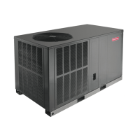
Remove these panels
for downflow duct
applications
Supply
Return
Duct Cover Installation
Down Discharge Applications
Cut insulation around bottom openings and remove panels
from the bottom of the unit, saving the screws holding the
panels in place.
NOTE: Single phase models require installation of horizontal
duct kit #20464501PDGK (medium chassis) and
#20464502PDGK (large chassis).
DUCT WORK
Duct systems and register sizes must be properly designed
for the C.F.M. and external static pressure rating of the unit.
Duct work should be designed in accordance with the
recommended methods of Air Conditioning Contractors of
America Manual D (Residential) or Manual Q (Commercial).
All duct work exposed to the outdoors must include a
weatherproof barrier and adequate insulation.
A duct system should be installed in accordance with
Standards of the National Board of Fire Underwriters for the
Installation of Air Conditioning, Warm Air Heating and
Ventilating Systems. Pamphlets No. 90A and 90B.
The supply duct from the unit through a wall may be installed
without clearance. However, minimum unit clearances as
shown in the Appendix must be maintained. The supply duct
should be provided with an access panel large enough to
inspect the air chamber downstream of the heat exchanger. A
cover should be tightly attached to prevent air leaks.
For duct flange dimensions on the unit refer to the Unit
Dimension illustration in the Appendix.
For down discharge applications, the duct work should be
attached to the roof curb prior to installing the unit. Duct work
dimensions are shown in the roof curb installation manual.
If desired, supply and return duct connections to the unit may
be made with flexible connections to reduce possible unit
operating sound transmission.
FILTERS
Filters are not provided with unit and must be supplied and
externally installed in the return duct system by the installer. A
field-installed filter grille is recommended for easy and
convenient access to the filters for periodic inspection and
cleaning. When installing filters, ensure the air flow arrows
on the filter are pointing toward the circulator blower.
Refer to the unit filter size chart below for filter size information.
NOMINAL SIZE (INCHES) NOMINAL AREA (SQ. FT.)
10x20 1.4
14x20 1.9
14x25 2.4
15x20 2.1
16x20 2.2
16x25 2.8
20x20 2.8
20x25 3.5
25x25 4.3
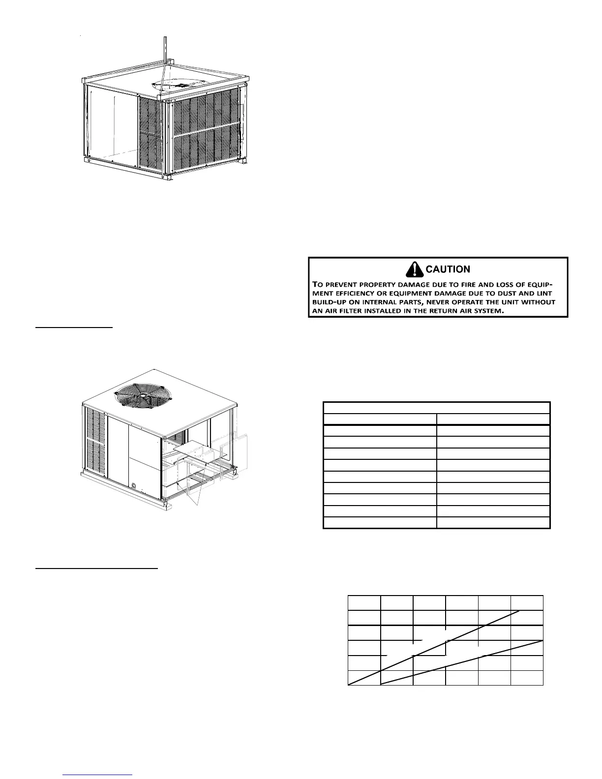
MINIMUM FILTER SIZE
NOTE: Filters must have adequate face area for the rated
quantity of the unit. See the air delivery table below for
recommended filter size. Size the filters in accordance with
their manufacturer recommendations. Throwaway filters must
be sized for a maximum face velocity of 300 feet per minute.
500 1000 1500 2000 2500 3000 3500
7
6
5
4
3
2
D
I
S
P
O
S
A
B
L
E
F
I
L
T
E
R
P
E
R
M
A
N
E
N
T
F
I
L
T
E
R
Airflow - SCFM
N
o
m
i
n
a
l
F
i
l
t
e
r
A
r
e
a
S
q
u
a
r
e
F
e
e
t