44
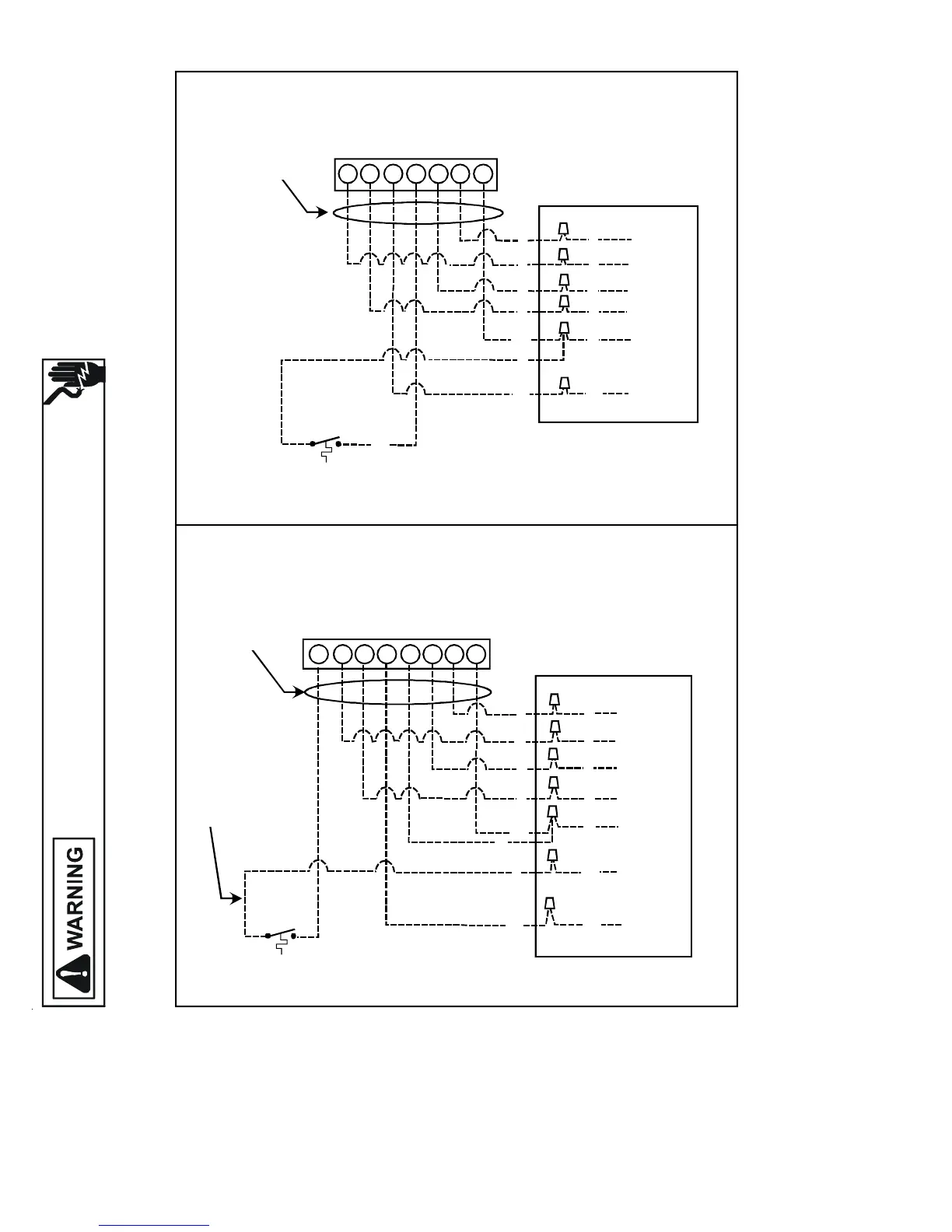
WIRING DIAGRAMS
HIGH VOLTAGE!
DISCONNECT ALL POWER BEFORE SERVICING OR INSTALLING THIS
UNIT. MULTIPLE POWER SOURCES MAY BE PRESENT. FAILURE TO
DO SO MAY CAUSE PROPERTY DAMAGE, PERSONAL INJURY OR DEATH.
OT18-60A OUTDOOR THERMOSTAT
BLUE
WHITE
ORANGE
GREEN
YELLOW
RED
SEE NOTE 1
#18 GAUGE 7 WIRE
REQUIRED FOR
HEAT PUMPS
PACKAGE SYSTEM WIRING DIAGRAM - 1 STAGE ELECTRIC HEAT
TYPICAL HP
ROOM THERMOSTAT
OUTDOOR THERMOSTAT
CLOSE ON TEMPERATURE FALL
12
YO
CW1G
R
E
R
Y
Y
R
G
O
O
G
W
BR
BL
BL
R
PACKAGE UNIT
LOW VOLTAGE
JUNCTION BOX
BL
W2 C RYO W1G E
TYPICAL HP
ROOM THERMOSTAT
12
OUTDOOR THERMOSTAT
CLOSE ON TEMPERATURE FALL
PACKAGE UNIT
LOW VOLTAGE
JUNCTION BOX
BLUE
BROWN
WHITE
ORANGE
GREEN
YELLOW
RED
SEE NOTE 1
#18 GAUGE 8 WIRE
FOR HEAT PUMPS
PACKAGE SYSTEM WIRING DIAGRAM - 2 STAGE ELECTRIC HEAT
ABOVE 10 KW
SEE NOTE 2
R
Y
G
O
O
Y
G
R
BL
BL
BR
R
W
BR
W
NOTES:
1) "O" and "E" used on heat pumps only.
2) Connect wire from terminal #1 on outdoor thermostat to the white
wire on package units if single stage indoor thermostat is used.
Color Codes
R - Red
Y - Yellow
BL - Blue
BR - Brown
O - Orange
W - White
G - Green

 Loading...