Do you have a question about the Gorilla GR 2560-B and is the answer not in the manual?
Congratulates the user and details the lifetime limited warranty for Gorilla Rack products against defects.
Provides advice on assembly lubricants, protection, rivets, surface, and loading, plus warnings on outdoor use.
Initiates frame assembly by joining short rivet beams to angle posts, ensuring proper flange orientation and rivet seating.
Connects long double rivet beams to the bottom end assembly, incorporating angle posts and short double rivet beams.
Attaches short double rivet beams to the top keyholes of angle posts, ensuring flanges are up and rivets are properly seated.
Installs two short double rivet beams at the desired height with flanges oriented upwards, securing them with a rubber mallet.
Assembles the add-on unit end using angle posts and short double rivet beams, following specific keyhole placements.
Secures long double rivet beams to the top keyholes of the angle posts for the add-on unit, ensuring all beams are locked.
Utilizes tie pins to connect the primary end and add-on unit, ensuring stability and proper alignment.
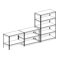
Finishes the assembly by adding post caps to the top of the corner posts and placing shelf decks.
Commences frame assembly by connecting short rivet beams to angle posts at the bottom, ensuring correct flange and rivet positioning.
Attaches long double rivet beams to the bottom end assembly, integrating angle posts and long double rivet beams.
Constructs the top end assembly by joining short double rivet beams to angle posts, specifying rivet use for connections.
Connects the top end assembly to the bottom assembly by inserting rivets into keyholes and securing the joints.
Adds two long double rivet beams to the mid section, using specified keyholes between the top and bottom assemblies for structural support.
Installs two additional long double rivet beams to the top keyholes of the angle posts for enhanced structural integrity.
Attaches the remaining short and long double rivet beams to the angle posts at desired positions to form the shelves.
Finishes the storage rack by placing post caps on the top of the corner angle posts and installing the shelf decks.
| Brand | Gorilla |
|---|---|
| Model | GR 2560-B |
| Category | Racks & Stands |
| Language | English |