4 GMC-I Messtechnik GmbH
1 Application
The A2000 measuring instrument is used for the analysis and monitoring of 3-phase current systems. It
can be operated with internal transformers in 3-phase current systems of up to 5 A and 500 V nominal
vo
ltage, and can perform measurements in medium-voltage systems in combination with external cur-
rent and voltage transformers.
The A2000 acquires voltages, curr
ent, frequency and phase displacement in 3 and 4-wire systems. It
calculates active, reactive and apparent power, active and reactive energy, as well as the power factor
for the individual phases based upon these values.
An FFT (= Fast Fourier Transformation) is performed
on the basis of the currents and phase voltages
and the harmonic waves are determined up to the 15
th
harmonic. For the phase voltages, the harmonic
distortions of the individual harmonics are indicated as well as the total harmonic distortion, for the cur-
rents, the respective RMS values are indicated.
Transformation ratios can be entered to the instrument, which means that all primary measurement data
can be displayed directly at the A2000. Maximum values are stored to memory for every measured or cal-
culated quantity. If limit values are exceeded, corrective action can be triggered via relay outputs. Energy
m
eters, recorders, data loggers and control loops can be connected to the digital and analog outputs. Via
the analog outputs 2 random measured quantities can be acquired by means of standard signal genera-
tor or temperatures via Pt1000 sensor. The instrument can be integrated into a field bus system or a LON
ne
twork with the communications interfaces, or its parameters can be configured with a PC.
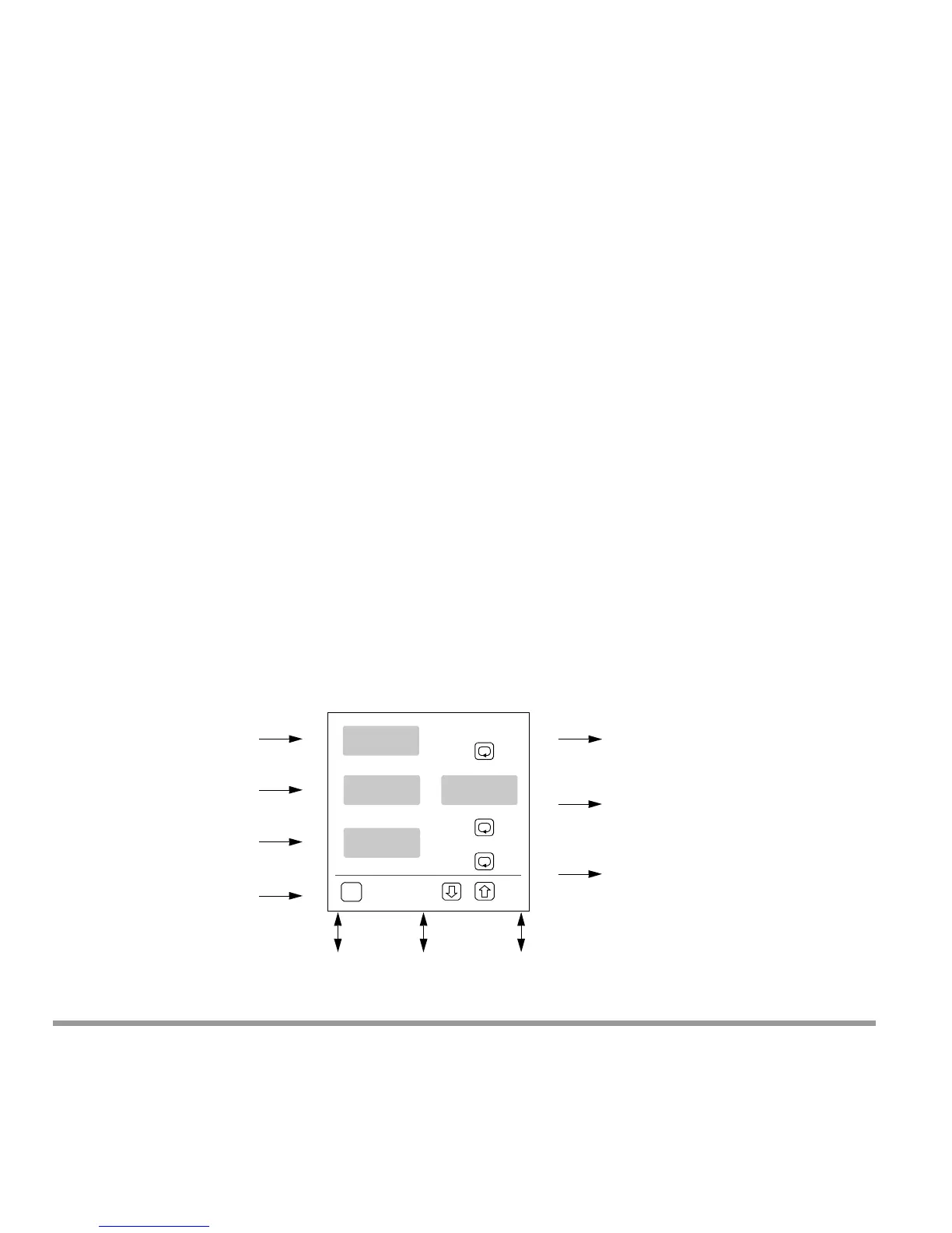
2 Instrument Description
2.1 Instrument Overview