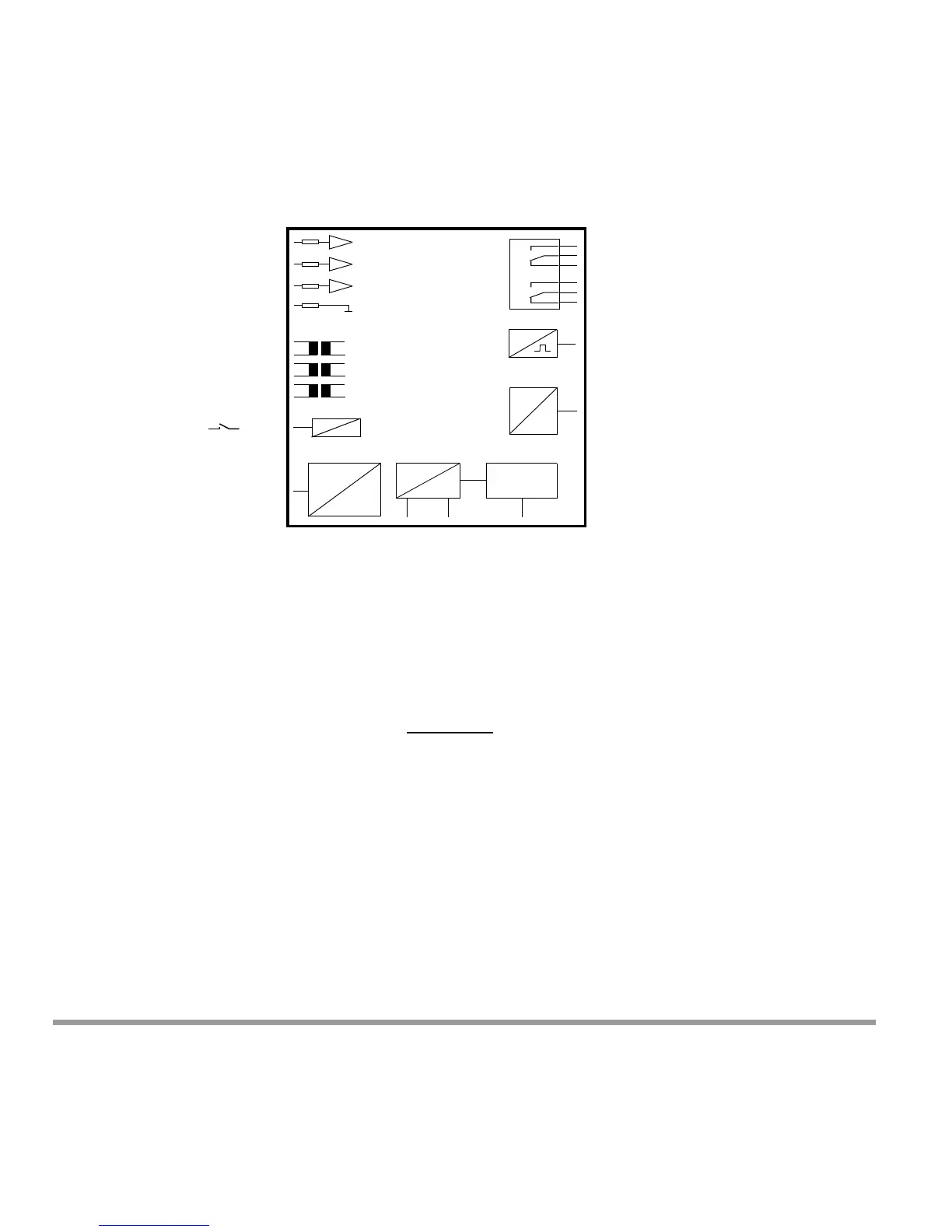
Supply
Power
D
A
L1
L2
L3
N
I1
I2
I3
Synchronizing
Input
Analog Outputs
A1, A2, (A3, A4 optional)
Analog inputs
(Option In1, In2 )
common reference point
Limit Value Relay 1
Limit Value Relay 2
Pulse Outputs
S01, S02 (optional)
common reference point +
LON or
Profibus-DP-
Interface
(optional)
RS232, RS485
Interface
Voltage
Inputs
Current
Inputs
Power Supply
(per serial plate specs)
Attention:
The device is not equipped
with an integrated circuit-
breaker
6Interface Description
The following sub-chapters include a brief description of the interfaces.
Please refer to the following manuals on our
homepage if you require a detailed description of the inter-
face protocols:
Communications Protocol per DIN draft 19244 Reference No. 3-349-125-03
Communications Protocol per EN 60870 Reference No. 3-349-128-03
Communications Protocol per Modbus – Mo
d 1 – Reference No. 3-349-225-03
Communications Protocol per Modbus – Mo
d 2 – Reference No. 3-349-129-03
LON Interface Reference No. 3-349-091-03
Profibus Interface Reference No. 3-349-092-03





 To Next Page