8 GMC-I Messtechnik GmbH
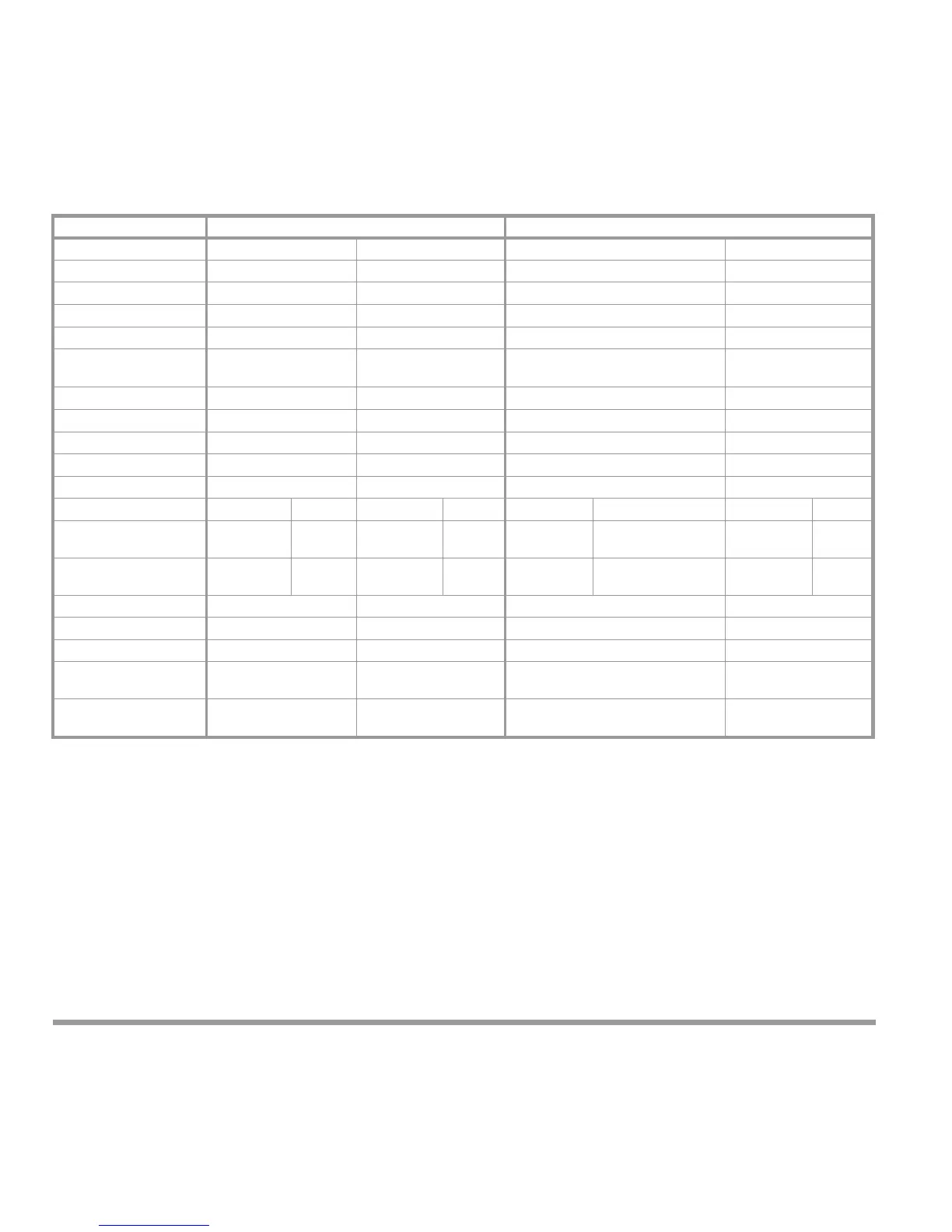
2.3 Available Measurement Data
Individual Phases Collective Values
Phase Voltages U1 ... U3 U1
max
... U3
max
U
4)
U
max
5)
Delta Voltages U12, U23, U31 U12
max
... U31
max
U
avg
4)
U
avg
max
5)
Phase Current I1 ... I3 I1
max
... I3
max
I
4)
I
max
5)
Averaged Phase Current I1
avg
... I3
avg
I1
avg max
... I3
avg max
I
avg
4)
I
avg max
5)
Neutral Conductor current
In In
max
— —
Averaged Neutral
Conductor Current
In
avg
In
avgmax
— —
Line Frequency — — f —
Active Power P1 ... P3 P1
max
... P3
max
P
P
max
Reactive Power Q1 ... Q3 Q1
max
... Q3
max
Q
Q
max
Apparent Power S1 ... S3 S1
max
... S3
max
S
S
max
Power Factors PF1 ... PF3 PF1
min
... PF3
min
PF
PF
min
Energy Mode L123
1)
LT H T
2)
L123
1)
LT H T
2)
L123
1)
LT H T
2)
L123
1)
LT H T
2)
Active Energy E
P1
... E
P3
– – – E
P
E
P L – ,
E
P L +
E
P H – ,
E
P H +
3)
– –
Reactive Energy E
Q1
... E
Q3
– – – E
Q
E
Q L – ,
E
Q L +
E
Q H – ,
E
Q H +
3)
– –
Intervalic Active Energy – – P
int
P
int
max
Interv. Reactive Energy – – Q
int
Q
int
max
Interv. Apparent Energy – – S
int
S
int
max
THD, 1
st
... 15
th
harmon. U1h ... U3h,
I1h ... I3h
U1hmax ... U3hmax,
I1hmax ... I3hmax
– –
In1, In2 Measured
V
alue 1, 2
6)
Max. Meas.
Value 1, 2
6)
— —
1)
L123 = individual phases L1, L2, L3
2)
LTHT = low tariff (LT) high tariff (HT)
3)
L = low tariff, H = high tariff, + = import, – = export
4)
only via interface and as a source for relay and analog output
5)
only via interface
6)
Value range depends on configuration
• The determination of measured and calculated quantities is performed in accordance with DIN
40110 part 1,2 4.96 (non-sinusoidal quantities).
• PEN conductor current is not taken into consideration fo
r the calculation of collective phase current
and collective apparent power.
• The averaging of currents I1
avg
I3
avg
, In
avg
is performed in the same manner as with a bimetallic
indicator, with a setting time of approx. 10 min relative to 99% of the final value.
 Loading...