grace design m902
owner’s manual
5
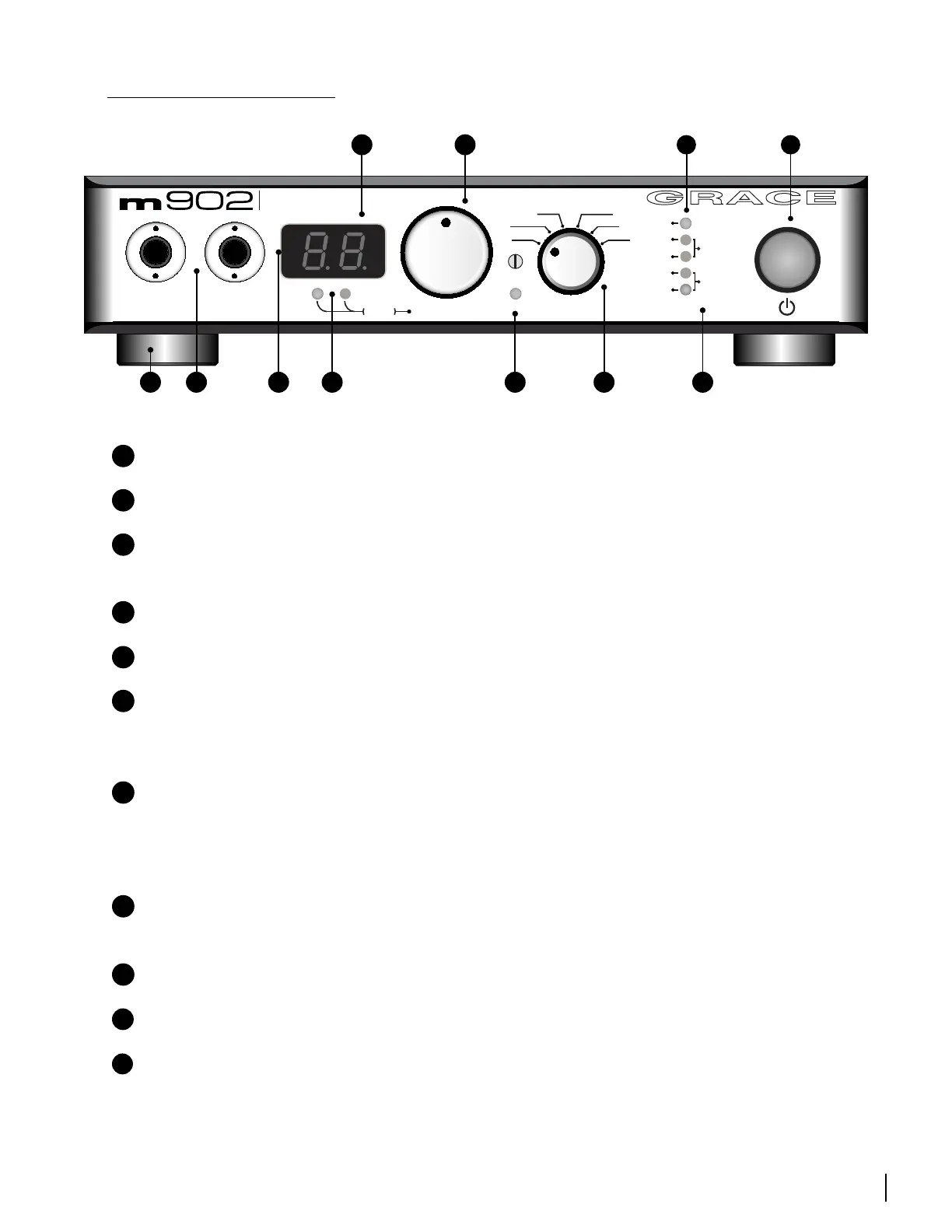
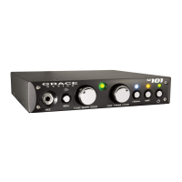
m902 FRONTPANEL
A
ILLUMINATED POWER SWITCH -
illuminates green when unit is powered on.
B
S-LOCK INDICATOR LED -
illuminates when s-lock is active.
C
SAMPLE RATE INDICATOR LEDS -
auto sample rate detection from selected digital input
source.
D
ROTARY INPUT SELECTOR SWITCH -
selects between all available inputs.
E
CROSSFEED INDICATOR LED -
crossfeed circuitry is user activated in submenu.
F
OUTPUT LEVEL/EDIT ROTARY ENCODER -
This stepped rotary encoder controls the
selected output level in .5dB increments. This encoder is also used to adjust other settings found
in the submenu.
G
OUTPUT LEVEL/SUBMENU DISPLAY -
This blue, 2 digit display shows the current relative
output level values based on the position of the main level rotary encoder. The range of this
display is 0 to 99. Note the decimal represents a 0.5dB increment. This display is also used to give
the user information in the submenu.
H
OUTPUT SELECTION LEDS –
These LEDS indicate which output is currently selected by the
user and under interface control.
I
INFRARED REMOTE RECEIVER –
Receiver used for optional wireless remote control.
J
HEADPHONE OUTPUTS –
Two stereo headphone output jacks wired in parallel.
K
FEET -
four custom machined removable metal feet with neoprene inserts.
B
FS
44
48
88
96
176
192
-Lock
INPUT
AES
BAL
UNBAL
S/PDIF
TOS
USB
xfeed
VOLUMEOUTPUTS
phonesline
push
reference headphone
amplifier
s
G
H
D
EI
C
F
A
J
K