308–167
INSTALLATION
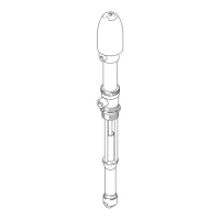
Before installing any air line components, blow out the
pipe
line to remove scale and other debris. Use pipe com
-
pound
or tape
sparingly and only on male threads. Install
the
regulator in the pipe line so the flow is in the
direction
of the arrow stamped on the body. Locate the regulator
as
close as possible to the equipment it serves.
Mounting brackets and nuts are available. See page 8.
To
reduce
the risk of serious bodily injury
, including
fluid
injection, splashing fluid in the eyes or on the
skin,
or injury from the pump starting unexpectedly
,
be sure your system includes a bleed–type
master
air valve
.
Install
the air valve
between the air regulator outlet
and the device the regulator is serving. When re-
lieving system air pressure, close the bleed–type
master
air valve to fully relieve air pressure.
WARNING
To
provide the user with a variety of
assembly options, a
bleed–type master air valve is not included with all regu
-
lator assemblies. See ACCESSORIES to order this
valve.
Another bleed–type master air valve may also be
installed
upstream from the air controls to isolate them for
servicing.
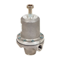
Be
sure the air to the
regulator is clean. Erratic regulator
operation
or loss of regulation is usually caused by dirt
in
the disc area. To clean the regulator, see the REPAIR
section
on page 4.
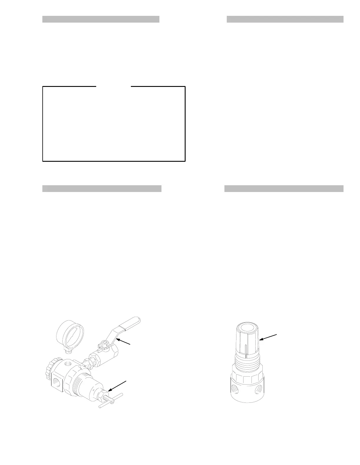
ADJUSTMENT
Relieving
Pressure
1. Close
the bleed–type
master air valve to bleed air be
-
tween
the valve to the device it is serving.
2. Trigger
the gun or dispense valve and open any
fluid
drain
valves to relieve fluid pressure.
Adjusting Pressure with a T-Handle Regulator
3. Loosen
the locknut.
4. To increase the regulated air pressure, turn the
T-handle
clockwise.
5. To decrease the regulated air pressure, turn the
T-handle
counterclockwise.
6. T
ighten the locknut to lock in the adjustment.
LOCKNUT
BLEED–TYPE
MASTER
AIR V
ALVE
(Shown open)
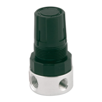
Adjusting
Pressure with a Knob–type Regulator
1. If the knob does not have a screw, pull the knob
up
to adjust. When the adjustment is complete, push
the
knob down to lock it in place.
2. If the knob has a cross–head screw, loosen the
screw 1/4 turn and the adjust the knob. Tighten the
screw
to lock in the adjustment.
3. To increase the regulated air pressure, turn the
knob
clockwise.
4. To decrease the regulated air pressure, turn the
knob
counterclockwise.
KNOB