NOTE:
To install a200 Series
Reel
into a K
-
Frame Enclo
-
sure, part no. 206
-
604, order the
Hose
Retainer
Kit, part no.
220-897. See manual 307-844.
supplied with the
kit,
for installation instructions.
1.
Select the reel bank mounting location.
If
the ceil
-
ings are very high, Suspend a suitable support struc
-
ture for the reels,
so
the hoses will be long enough
to
reach your service area.
The
reel bank should be mounted in a one
-
lift service
See
Fig
1.
In
a two
-
lift bay, mount the bank equal dis-
bay, at least
6
ft
(1.9 m) from the center line
of
the
lift.
tance between the lifts.
A
bank of all motor
oil
reels
should be mounted about 5
ft
(1.5 m) from the center
bracket
to
secure the mounting base to an I
-
beam
is
of
the lift, toward the front of the
lift
rails.
A
mounting
available.
See
ACCESSORIES,
page 25.
-.
6'
(1.9
m minimum
JOR.
1 UFTY
I
CENTER
BETWEEN
TWO
LIFTS
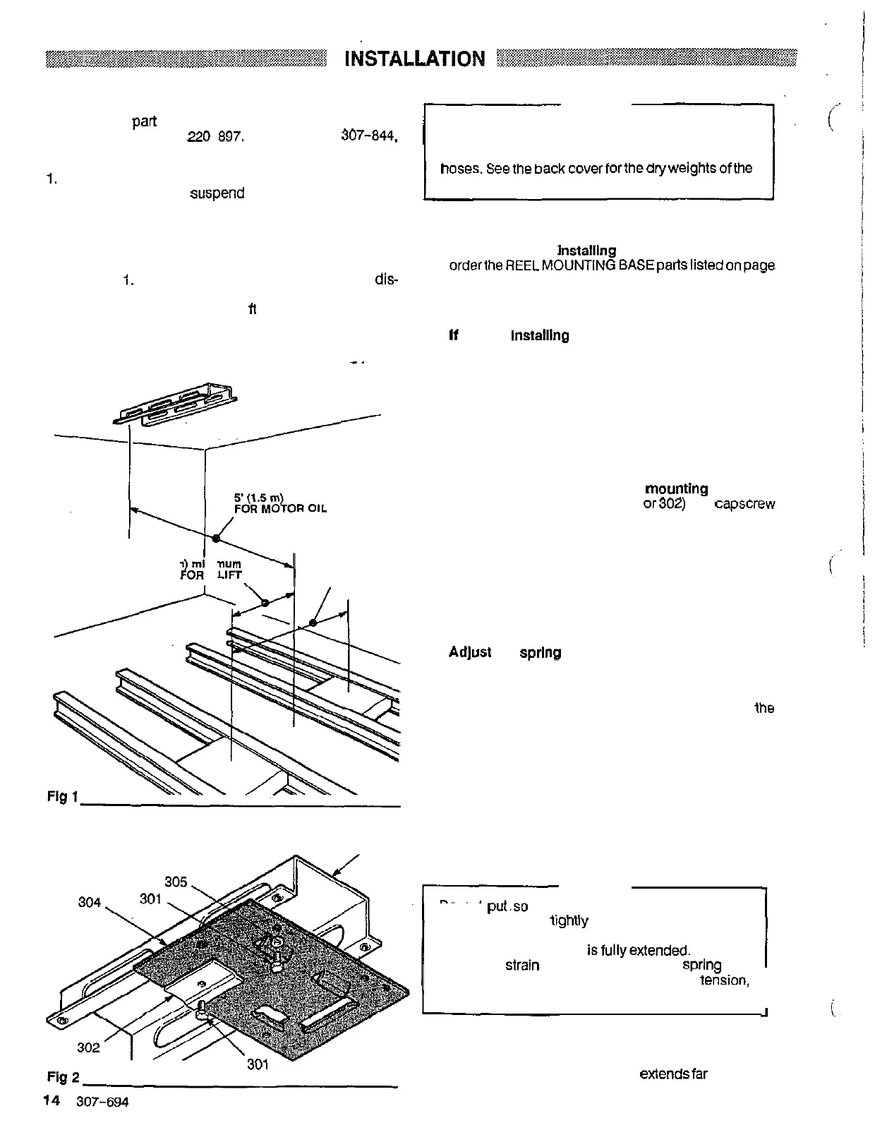
303
CAUTION
Be
sure the mounting surface is strong enough
to
support the reels. the weight of the lubricants, and
the stress caused by hard pulls on the service
hoses.Seethebackcoverforthedryweightsofthe
hose reel assemblies.
2.
If
you are
NOT
installlng
a
hose reel enclosure,
25 and install the frame (303) and base plate (304) as
OrdertheREELMOUNTlNGBASEpartsiistedonpage
shown in Fig 2.
reel base (103 or 304) to the mounting channel
(A),
It
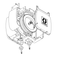
you are lnstalllng the hose reel enclosure,
bolt the
using the lockwashers
(B)
and screws (C) which are
supplied with the mounting channel. See Fig 3.
3.
If
you are Installing permanent supply lines,
drill
1.5
in.
(38 mm) diameter
holes
through the ceiling on
the inlet side of the reels.
4.
Slide the hose reel onto the mountlng base
and
(105 or
301).
Tighten the screw firmly.
See
Fig 3.
install the hold
-
down plate (104
or302)
and capscrew
5.
Connect the supply line
to
the inlet hose of the reel.
NOTE:
All
other hose reels listed in this manual are
supplied with a Hose inlet Kit.
6.
Adjust the sprlng tension
of
the reel.
NOTE:
If
you are installing a hose on a bare reel, connect
the Service hose to the swivel (31). Then wrap
the
fully and latch
it.
Wrap one or
two
loops around
hose
loosely around the flange. Extend the hose
the hose reel, then retract the hose again.
Check the spring tension: the hose must pull out fully
and retract fully. Wrap
ONE
more loop, extend the
hose, and latch
it.
Do
this as many times
as
necessary
until the spring has the desired tension.
CAUTION
Do
not put.so many loops onto the reel that the
spring winds
up
tigMly before the hose is fully
extended.
A
spring that is wound
too
tightly stops
rotating before the hose
isfullyextended. That puts
excessive
strain
on
the hose and reel sprina and
could damage the reel.
To
decrease tekion,
remove two or three loops of hose from the reel.
I
7.
Install
the
hose stop
(D)
and dlspenslng valve.
Po
-
sition the hose stop
so
the hose extendsfar enoughfor
all operators
to
reach
it.
See
Fig
3.
 Loading...