EasyManua.ls Logo

Graco REACTOR E-20 User Manual

Graco REACTOR E-20
74 pages
To Next Page IconTo Next Page
Page #1 background imageLoading...
Page #1 background image
Graco Inc. P.O. Box 1441 Minneapolis, MN 55440-1441
Copyright 2003, Graco Inc. is registered to I.S. EN ISO 9001
309574L
Repair - Parts
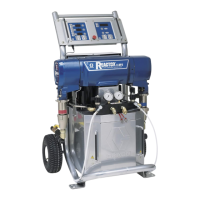
Electric, Heated, Plural Component
Proportioner
For spraying polyurethane foam and polyurea coatings.
Not for use in explosive atmospheres.
Important Safety Instructions:
Read all warnings and instructions in this manual. Save these
instructions.
See page 2 for Table of Contents and page 3 for List of Models.
TI3764a-1

Questions and Answers:

Graco REACTOR E-20 Specifications

General IconGeneral
BrandGraco
ModelREACTOR E-20
CategoryPaint Sprayer
LanguageEnglish

Summary

Important Safety Instructions

Equipment Models

E-XP Series Models

Lists specifications for E-XP Series models, including voltage, amps, and pressure ratings.

Manual Conventions

Warning Symbols

Explains the meaning of warning symbols used in the manual.

Caution Symbols

Explains the meaning of caution symbols used in the manual.

Note Symbols

Explains the meaning of note symbols used in the manual.

Supplied Manuals

Lists the manuals that are shipped with the Reactor Proportioner.

Related Manuals

Safety Warnings

Skin Injection Hazard

Details risks and precautions associated with high-pressure fluid injection.

Fire, Explosion, and Electric Shock Hazard

Outlines hazards related to flammable solvents, fumes, and electrical components.

Safety Warnings

Equipment Misuse Hazard

Highlights dangers and consequences of improper equipment use and modifications.

Burn Hazard

Warns about the risk of burns from heated fluid and equipment surfaces.

Toxic Fluid or Fumes Hazard

Addresses hazards from exposure to toxic fluids or fumes and handling procedures.

Personal Protective Equipment

Specifies required PPE for safe operation and servicing of the equipment.

Before Beginning Repair

Flushing Procedure

Pressure Relief Procedure

Temperature Control Diagnostic Codes

E01: High Fluid Temperature

Troubleshooting steps for the E01 error code indicating high fluid temperature.

Temperature Control Diagnostic Codes

E02: High Hose Current

Troubleshooting steps for the E02 error code related to high hose current.

E03: No Hose Current

Troubleshooting steps for the E03 error code indicating no hose current.

Temperature Control Diagnostic Codes

E04: Sensor or Thermocouple Not Connected

Steps to diagnose and fix E04 error for unconnected sensors or thermocouples.

Temperature Control Diagnostic Codes

E05: Board Overtemperature

Troubleshooting for the E05 error code indicating board overtemperature and board shutdown.

Motor Control Diagnostic Codes

Alarms

Describes motor control alarms, their function, and how to clear them.

Warnings

Explains motor control warnings, their behavior, and clearing procedures.

Motor Control Diagnostic Codes

E21: No Component A Transducer

Troubleshooting steps for the E21 error code related to missing component A transducer.

E22: No Component B Transducer

Troubleshooting steps for the E22 error code related to missing component B transducer.

E23: High Pressure

Diagnostic steps for the E23 error code indicating high system pressure.

E24: Pressure Imbalance

Troubleshooting the E24 error code for pressure differences between components.

Motor Control Diagnostic Codes

E25: High Line Voltage

Diagnosing and resolving the E25 error for high input line voltage.

E26: Low Line Voltage

Diagnosing and resolving the E26 error for low input line voltage.

E27: High Motor Temperature

Troubleshooting steps for the E27 error indicating high motor temperature.

E28: High Current in Motor

Steps to diagnose and resolve the E28 error for high motor current.

Motor Control Diagnostic Codes

E29: Brush Wear

Troubleshooting the E29 error for motor brush wear.

E30: Momentary Loss of Communication

Diagnosing the E30 error for temporary communication loss between components.

E99: Loss of Communication

Troubleshooting steps for the E99 error indicating a complete loss of communication.

Troubleshooting

Repair Procedures

Pump Removal

Step-by-step instructions for safely removing the pump from the Reactor unit.

Repair Procedures

Pump Installation

Detailed guide for correctly installing the pump assembly onto the Reactor.

Repair Procedures

Drive Housing

Instructions for removing and installing the drive housing assembly.

Repair Procedures

Motor Brushes

Procedure for removing and installing motor brushes, including inspection and replacement.

Repair Procedures

Circuit Breaker Module

Guide for testing, replacing, and troubleshooting circuit breaker modules.

Repair Procedures

Electric Motor

Steps for removing and installing the electric motor, including safety precautions.

Repair Procedures

Motor Control Board

Instructions for replacing the motor control board and setting DIP switches.

Repair Procedures

Transducers

Procedure for replacing pressure transducers, including testing and connection checks.

Repair Procedures

Fan

Steps for removing and installing the fan, including fuse checks.

Repair Procedures

Temperature Control Board

Guide for replacing the temperature control board and understanding its LEDs.

Repair Procedures

Heater

Instructions for testing and replacing the heater element.

Repair Procedures

Thermocouple

Procedure for testing and replacing the thermocouple and sensor housing.

Repair Procedures

Overtemperature Switch

Steps to test and replace the overtemperature switch.

Repair Procedures

Heated Hose

Procedure for checking hose connectors and FTS cables for continuity.

Repair Procedures

Fluid Temperature Sensor (FTS)

Guide for testing and replacing the Fluid Temperature Sensor (FTS).

Repair Procedures

Wire Harness Check

Tests for hose continuity, transformer harness continuity, and current sensor continuity.

Repair Procedures

Transformer Primary Check

Procedure to check the primary circuit of the transformer.

Transformer Secondary Check

Procedure to check the secondary circuit of the transformer and voltage readings.

Repair Procedures

Replace Transformer

Step-by-step guide to safely replace the transformer unit.

Repair Procedures

Display Module

Instructions for replacing the display module and its components.

Repair Procedures

Red Stop Button

Procedure for removing and replacing the red stop button.

Parts List

Reactor Assembly

Diagram and part numbers for the main Reactor assembly.

Reactor Assembly

Common Parts

List of parts that are common to all Reactor models.

Reactor Assembly

Parts that Vary by Model

Table detailing parts specific to different Reactor models based on part number.

Technical Data

Graco Standard Warranty

Graco Information

Related product manuals