7308546
Installation–Typical Layout
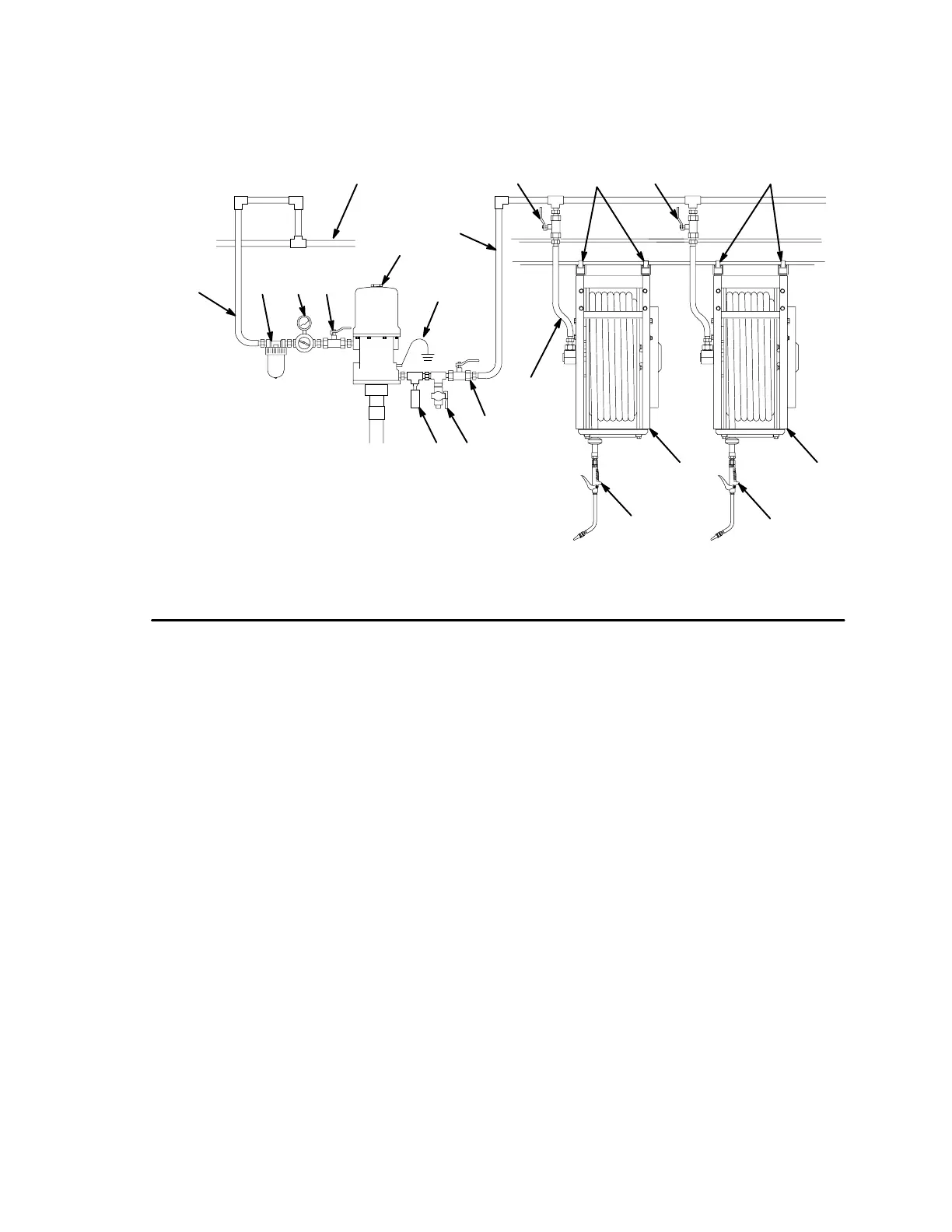
The installation shown in Fig.1 is only a guide for selecting and installing a hose reel system. The components and
accessories shown are the minimum requirements for all systems; however, it is not an actual system design.
Contact your Graco distributor for assistance in designing a system to suit your needs.
KEY
A Main air supply line
B Pump air supply line
C Air filter
D Air regulator
E Bleed-type master air valve (required)
F Pump
G Pump grounding wire (required)
H Thermal relief valve (required)
J Dump valve (required)
K Fluid shut-off valve
L Fluid line
M Hose reel
N Dispensing valve
P Mounting channel/base
Q Flexible inlet hose
M
H
Fig. 1
NOTE: Parts are not proportional.
B
A
CDE
F
G
J
L
05266
M
N
PP
K
N
K K
Q