Installation
311304C 5
Installation
When unpacking pump, check for shipping damage.
Report any shipping damage to delivering carrier imme-
diately.
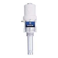
Mounting Pump
1. Apply fuel compatible sealant to large thread on
bung adapter (9) (2 in. x 1-1/2 in. reducer fitting).
Install bung adapter on fuel tank.
2. Assemble suction tube sections by applying PVC
cement (supplied with your pump) to the inside
diameter of the PVC couplers. Make sure PVC
cement is applied to the complete inside diameter
and slide the pipe sections into the coupler with a
twisting motion.
3. Cut the suction tube so that it is 2 in. (55 mm) from
the bottom of the tank when installed in the tank.
4. Insert inlet gasket (7f) into union nut (1k). Apply a
fuel compatible sealant to the threads on the suction
tube assembly (5c) and screw the suction tube into
the pump inlet (1j).
5. Insert suction tube attached to pump through bung
adapter (9) into tank. Position pump as desired and
tighten union nut (1k) on bung adapter (9).
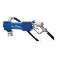
Mounting Hose and Nozzle
1. Apply fuel compatible sealant to male threads on
the street elbow fitting (1e) and screw fitting into the
3/4 in. npt outlet port on the top of pump. Do not
over tighten.
2. Apply fuel compatible sealant to threads on both
ends of the hose assembly. Screw one end of hose
into the female thread on the fitting (1e) and tighten.
3. Screw nozzle onto the other end of hose and
tighten.
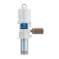
Electrical Installation
12 VDC and 24 VDC
To install wiring for a negative ground system:
1. Ensure pump switch is OFF.
2. To remove electrical cover (2a), remove four bolts
(2c).
3. Strip 3 in. (76 mm) of outside insulation from power
cable (6c) from end opposite of fuse.
4. Strip 3/8 in. (10 mm) of insulation from red and black
wires.
5. Slide strain relief (6b) over end of power cable (6c)
on the end just stripped. Male thread of strain relief
should be toward stripped end.
6. Insert power cable through conduit thread in electri-
cal cover (2a). Connect wires from power cable to
wires from the motor using wire nuts (2e): red to red
and black to black.
7. Screw strain relief (6b) into electrical cover (2a).
CAUTION
Do not use a curb pump automatic shut-off nozzle
with this pump. Use of a curb pump automatic nozzle
may cause priming problems, reduced output flow,
and motor overheating. If an automatic shut-off nozzle
is required, use Graco part number 260082 (regular)
or 260083 (unleaded) or Catlow, Inc. part number
NCLF-1 (regular) or NCNLF-1 (unleaded).
CAUTION
• Ensure tank being used is clean and free of welding
slag.
• Ensure the tank has a vent to allow air into the tank
as the fuel is being pumped out. Failure to vent tank
will cause priming problems.
For tanks deeper than 36 in. (914 mm) you will
need a standard 1 in. (25 mm) pipe with 1 in. npt
threads on one end. Suction tubes longer than 60
in. (1.52 m) require a foot valve (Graco Part No.
260217) at the bottom of the tube to prevent loss of
prime.
Power cable can be cut to shorter length if 18 feet
(5.5 m) is not required. Cut to proper length and
proceed with steps 3 and 4.