RECTIFIER
(See Fig. 1) Now we come to the most popular application of the diode: rectifcation. Rectifcation is the conversion of alternating
current
(AC) to direct current (DC). This almost always involves the use of some device that only allows one-way fl ow of electrons.
As
we have seen, this is exactly what a diode does.
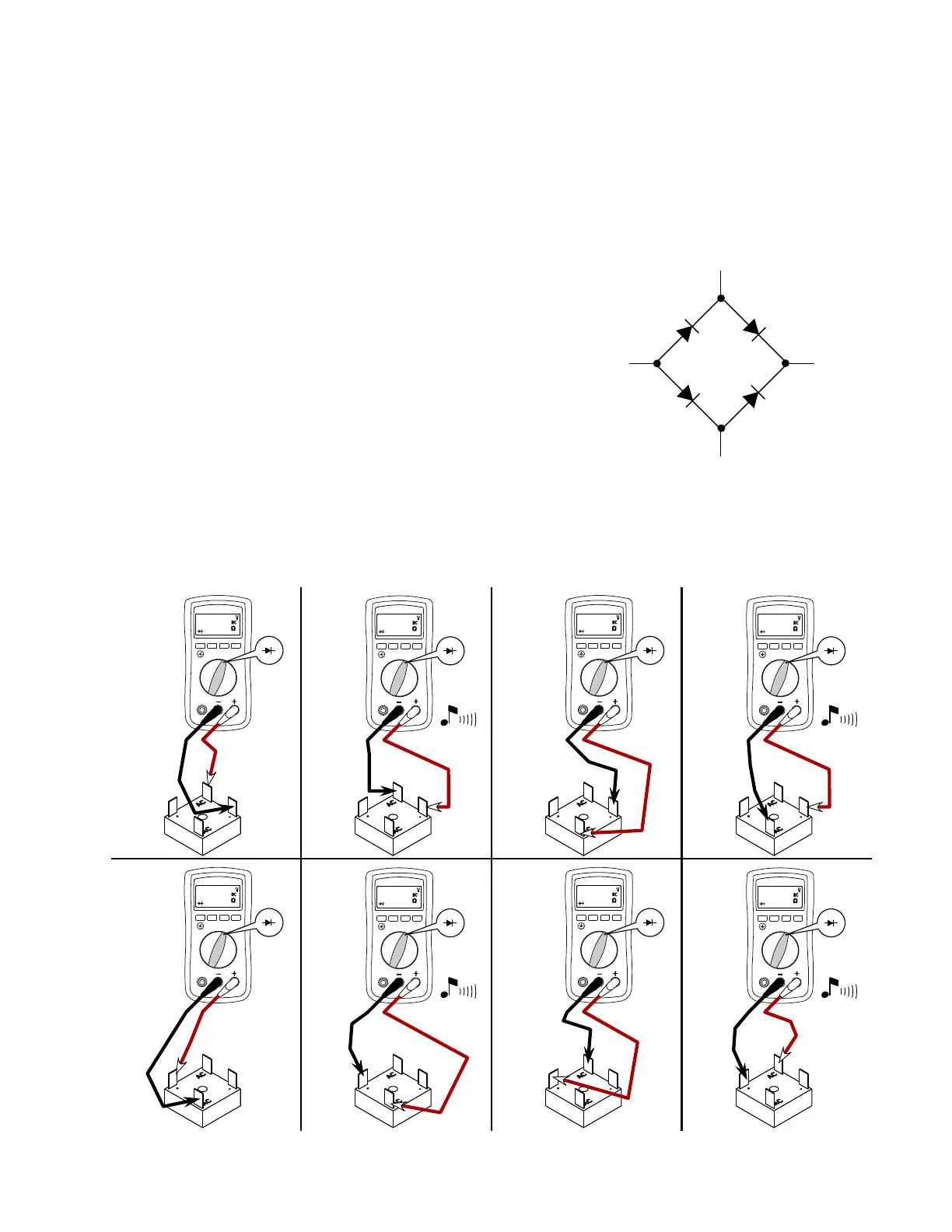
RECTIFIER TESTING:
The following instructions can be used to test any bridge rectifer.
Use a DC continuity test light or a VOM (on the R x 100 scale) for all tests.
Disconnect all wires from the recti
fer.
AC
AC
+
-
FI
G. 1
1 Connect test leads as shown in Figure A. If the meter beeps, the rectifer is
defective. If the meter does not beep, go to the next step.
2 Connect test leads as shown in Figure B. If the meter does not beep, the
recti
fer is defective. If the meter beeps, go to the next step.
3 Connect test leads as shown in Figure C. If the meter beeps, the rectifer is
defective. If the meter does not beep, go to the next step.
4 Connect test leads as shown in Figure D. If the meter does not beep, the
recti
fer is defective. If the meter beeps, go to the next step.
5 Connect test leads as shown in Figure E. If the meter beeps, the rectifer is
defective. If the meter does not beep, go to the next step.
6 Connect test leads as shown in Figure F. If the meter does not beep, the rectifer is defective. If the meter beeps, go to the next step.
7 Connect test leads as shown in Figure G. If the meter beeps, the rectifer is defective. If the meter does not beep, go to the next step.
8 Connect test leads as shown in Figure H. If the meter does not beep, the rectife r is defective. If the meter beeps, the rectifer is good.
0.000
OL OL
0.000
0.000
OL OL
0.000
FIG. A FIG. B FIG. C FIG. D
FIG
. E FIG. F FIG. G FIG. H
DC
DC
 Loading...