2 310724
Instructions
1. To relieve pressure:
a. Turn power switch OFF.
b. Unplug sprayer.
c. Turn Spray–Prime/Drain knob (A) down.
d. Hold metal part of gun firmly to a grounded
metal pail. Pull gun trigger to relieve pressure.
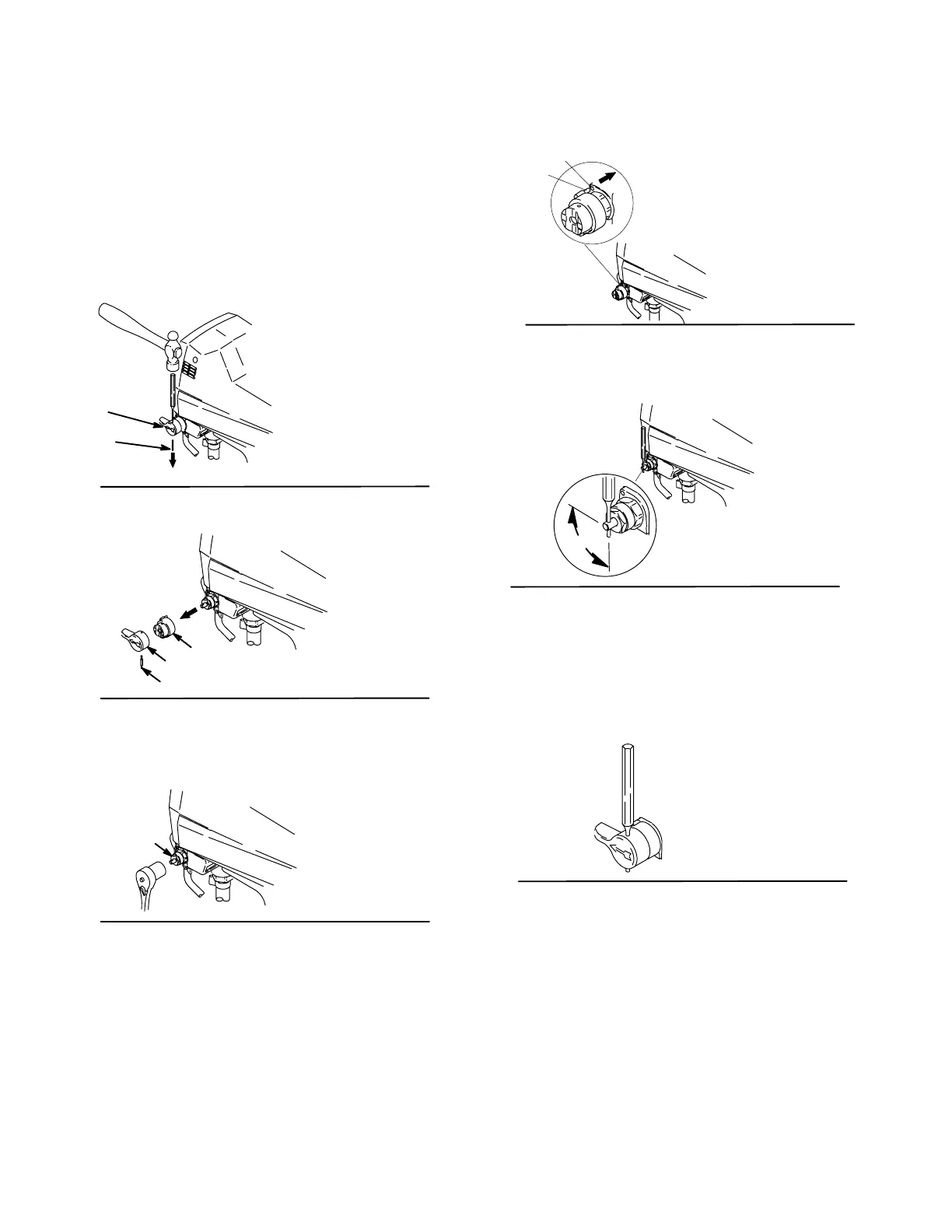
2. Turn knob (A) up (Spray position) (Fig. 1).
3. Using a 3/32 pin punch and hammer, remove
pin (B) (Fig. 1).
ti5854a
Fig 1
B
A
4. Remove knob (A) and base (C) (Fig. 2).
Fig 2
A
C
B
ti5854a
5. Using a 13/16 socket wrench, unscrew valve (6)
and remove from manifold. (Fig. 3). Be sure
gasket (8) and seat (7) do not stay in manifold.
Fig 3
6
ti5854a
6. Apply small amount of sealant (9) to threads of
valve (6). Using a 13/16 socket wrench, screw
valve into manifold. Torque to 185 in–lbs (21
N-m).
7. Install base (C) on valve (6), aligning pin (D) on
base (C) with hole (E) on manifold
(Fig.5).
Fig 4
D
E
ti5854a
8. Using 3/32 pin punch, rotate valve stem until hole
is perpendicular (Fig. 6).
Fig 5
90°
ti5854a
9. Install knob (A) over base (C). (Fig. 7).
Note: For the knob (A) to be aligned properly, the
knob should be in the Spray position.
10. Insert end of pin punch through hole in knob (A),
to make sure knob and valve stem are properly
aligned.
Fig 6
11. Intall pin (B) through hole in knob. Use a hammer
to tap pin (B) all the way through the knob (A).
When completely installed, the end of the pin will
be flush with the top of the hole in the knob.
All written and visual data contained in this document reflect the latest product information available at the time of publication.
Graco reserves the right to make changes at any time without notice.
GRACO INC. P.O. BOX 1441 MINNEAPOLIS, MN 55440–1441
www.graco.com
PRINTED IN USA 310724 03/2004, Revised 4/2005
 Loading...