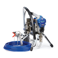
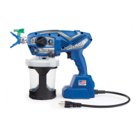
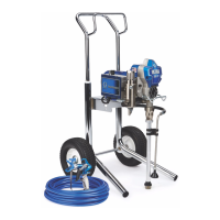
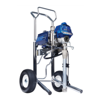
Sprayer
Description
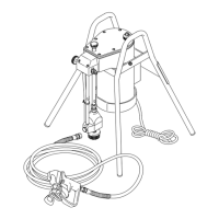
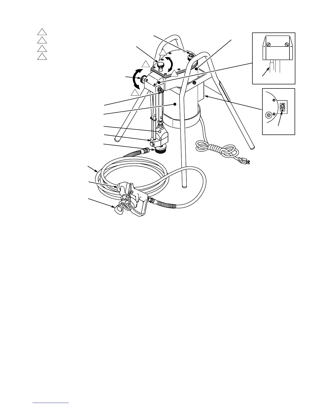
KEY
A Hydraulic
pump
B
Rac IV DripLess tip guard
and spray tip
4
Pressure control knob
5
Hydraulic oil fill cap
11
ON/OFF switch
18 Motor
21 Diaphragm
22
Paint pump
27 Strainer
59
Drain tube
63
Outlet valve
66
Bypass valve
67 Outlet
101
Paint hose
102
Spray Gun
59
27
66
4
63
A
5
102
101
B
18
11
21
22
Decrease the pressure (counterclockwise).
Increase the pressure (clockwise).
Open the valve (counterclockwise).
Close the valve (clockwise).
Motor
The
sprayer has a 1/2 hp, 120
V
, 60 HzAC, single phase,
1725
rpm motor (18).
The motor is supplied with a three-
wire power supply cord and a three-prong plug. The
sprayer
ON/OFF switch is located on the side
of the mo
-
tor.
The motor drives the hydraulic pump. The motor runs
continuously
when it
is turned on to keep the paint at the
desired
pressure.
Paint Pump
The
paint pump (22) is immersed into a 5 gallon paint pail,
so the pump is actually being pressure fed without the
mess
and trouble of pouring paint into a hopper
.
Hydraulic Pump
The hydraulic pump (A) is located inside the hydraulic
reservoir. The motor drives an eccentric bearing which
pushes
the piston in and out of the hydraulic pump. The
pump
reciprocates the hydraulic fluid to
operate the dia
-
phragm.
Diaphragm
The diaphragm (21) separates the hydraulic and paint
portions
of the paint pump. Hydraulic oil causes the dia
-
phragm to move up and down almost 30 times per sec-
ond,
no matter what pressure you are spraying at.
Pressure Control Knob
The paint pressure is regulated by turning the pressure
control knob (4) clockwise to increase the pressure and
counterclockwise to decrease the pressure.
Bypass V
alve
The
bypass valve (66) has two
functions: (1) to assist in
priming the paint pump during initial startup, and (2) to
provide positive relief of paint pressure from the gun,
hose,
and sprayer
.
Paint Hose
One electrically-conductive, nylon paint hose (101) is
supplied
with the sprayer Model 218–501. This 25 foot (7
m)
hose has a 1/4 inch ID, 1/4 npsm (fbe) couplings and
spring
guards on both ends.
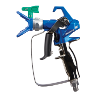
Spray Gun, Reverse-A-Clean (RAC) IV T
ip Guard
and Spray T
ip
The
spray gun supplied with Model 218–501
(102) has a
tough, lightweight plastic body. The gun has a trigger
safety lever which prevents accidentally triggering the
gun when the lever is set in the safe position. (See
WARNINGS,
page 4).
The
RAC IV T
ip Guard (B) uses high pressure fluid to un
-
clog
the spray tip without removing
it from the gun. (See
page
10). The RAC IV includes a safety
tip guard which
helps
reduce the risk of a fluid
injection injury
. A No. 215
spray
tip for use with latex paint is also includes.