3309251
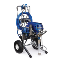
Component Identification and Function
ti2377a
K
E
H
B
A
D
J*
G
F
V
ti0866A
Fig. 1
U
N
M
PR S
W*
T
L
ti2377a
A Motor DC motor, permanent magnet, totally enclosed, fan cooled
B Drive Assembly Transfers power from DC motor to displacement pump
D Displacement Pump Transfers fluid to be sprayed from source through spray gun
E Fluid Outlet Spray gun is connected here
F Prime Valve Used to prime, drain and flush sprayer when open
G Fluid Filter Final filter of fluid to spray gun
H Pressure Adjusting Knob Controls fluid outlet pressure
J* Pressure Control/Display Controls motor speed to maintain fluid outlet pressure. Works with pressure ad-
justing knob. Displays pressure, gallons/liters, flush time and error codes.
K ON/OFF Switch Power switch that controls main power to sprayer
L 15/20A or 10/12A Switch Set to lower Amperage if circuit breaker trips when spraying (not all models)
M Airless Paint Spray Hose Grounded, conductive, nylon hose with spring guards on both ends
N Spray Gun High pressure spray gun with gun safety latch
P RAC X SwitchTip Uses high pressure fluid to clear tip clogs without removing tip from spray gun
R
HandTite Tip Guard
Tip guard reduces risk of injection injury
S Gun Safety Latch Gun safety latch inhibits accidental triggering of spray gun
T Power Cord & Hose Rack Holds wrapped power cord and paint hose for storage
U Suction Tube Transfers fluid to be sprayed from source to pump
V Drain Tube Fluid outlet used to drain and prime the sprayer
W*
AutoClean valve
Spray gun connection for timed back–flush of sprayer with automatic shut off
* Not available on all sprayers
 Loading...