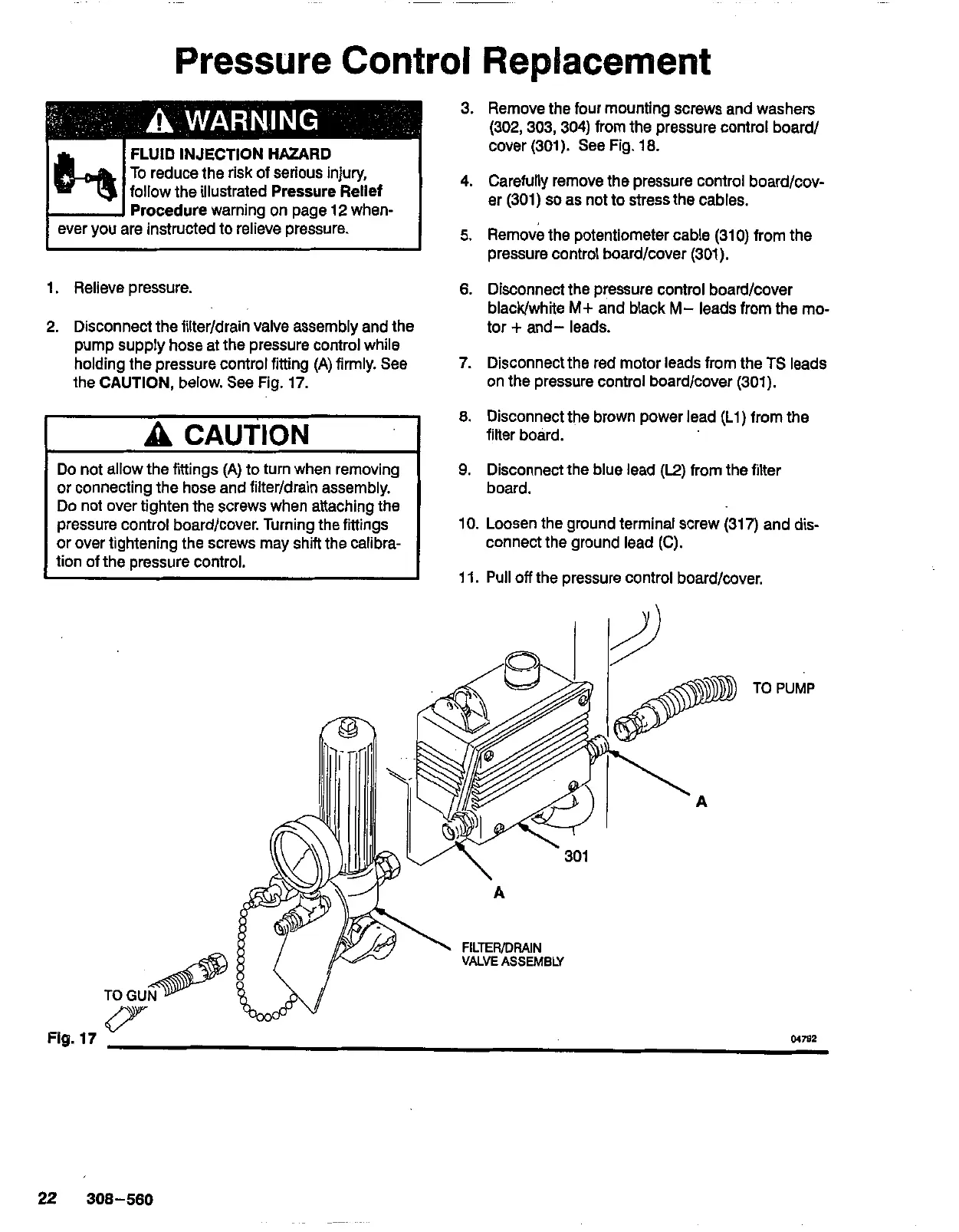
Pressure Control Replacement
3. Remove the four mounting screws and washers
(302,303,304) from the pressure control board/
cover (301).
See
Fig. 18.
4. Carefully remove the pressure control board/cov-
ocedure
warning on page 12 when-
er (301)
so
as not to stress the cables.
ever you are instructed to relieve pressure.
-
.-
I
5.
Remove the potentiometer cable (310) from the
pressure control board/cover (301).
1. Relieve pressure.
6.
Disconnect the pressure control board/cover
2. Disconnect the filter/drain valve assembly and the
blacWwhite
M+
and black
M-
leads from the mo-
pump supply hose at the pressure control while
tor
+
and- leads.
holding the pressure control fitting
(A)
firmly.
See
the
CAUTION,
below.
See
Fig. 17.
7. Disconnect
the
red motor leads from the
TS
leads
on the pressure control board/cover (301).
A
CAUTION
Do not allow the fittings
(A)
to turn when removing
or connecting the hose and filter/drain assembly.
Do
not over tighten the screws when attaching the
pressure control board/cover. Turning the fittings
or over tightening the screws may shift the calibra-
tion of the pressure control.
TO GU
fl
8.
Disconnect the brown power lead (Ll) from the
filter board.
9.
Disconnect the blue lead
(E)
from the filter
board.
10. Loosen the ground terminal screw (317) and dis-
connect the ground lead
(C).
11. Pull
off
the pressure control board/cover.
TO
PUMP
Fig.
17
v
M7W