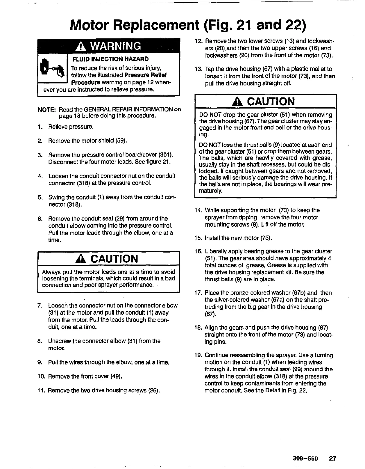
Motor
Replacement
(Fig.
21
and
22)
FLUID
INJECTION
HAZARD
To
reduce the risk of serious injury,
Procedure warning on page
12
when-
follow the illustrated Pressure Rellef
ever you are instructed to relieve pressure.
NOTE:
Read the GENERAL REPAIR INFORMATION on
page
18
before doing this procedure.
1.
Relieve pressure.
2.
Remove the motor shield
(59).
3.
Remove the pressure control board/cover
(301).
Disconnect the four motor leads. See figure
21.
4. Loosen the conduit connector nut on the conduit
connector
(318)
at the pressure control.
5.
Swing the conduit
(1)
away from the conduit
con-
nector
(318).
6.
Remove the conduit seal
(29)
from around the
conduit elbow coming into the pressure control.
Pull
the motor leads through the elbow, one at
a
time.
I
A
CAUTION
I
I
Always pull the motor leads
one
at a time
to
avoid
loosening the terminals, which could result in a bad
connection and poor sprayer performance.
I
7.
Loosen the connector nut on the connector elbow
(31)
at the motor and pull the conduit
(1)
away
from
the
motor.
Pull
the leads through the con-
duit, one at a time.
8.
Unscrew the connector elbow
(31)
from the
motor.
9.
Pull
the wires through the elbow, one at a time.
10.
Remove the front cover
(49).
11.
Remove the
two
drive housing screws (26).
12.
Remove the
two
lower screws
(13)
and lockwash-
ers (20).and then the
two
upper screws
(16)
and
lockwashers (20) from the front of the motor
(73).
13.
Tap the drive housing
(67)
with a plastic mallet to
loosen it from the front of the motor
(731,
and then
pull the drive housing straight
off.
A
CAUTION
the drive housing
(67).
The gear cluster may stay en-
DO NOT drop the gear cluster
(51)
when removing
gaged in the motor front end bell or the drive hous-
ing.
DO NOT
lose
the thrust balls
(9)
located at each end
The balls, which are heavily covered with grease,
of the gear cluster
(51)
or drop them between gears.
usually stay in the shaft recesses, but could be dis-
lodged.
If
caught between gears and not removed,
the balls will seriously damage the drive housing.
If
the balls are not in place, the bearings will wear pre-
maturely.
14.
While supporting the motor
(73)
to keep the
sprayer from tipping, remove the four motor
mounting screws
(8).
Lift
off
the motor.
15.
Install the new motor
(73).
16.
Liberally apply bearing grease to the gear cluster
total ounces of grease, Grease
is
supplied with
(51).
The gear area should have approximately
4
the driie housing replacement
kit.
Be
sure the
thrust balls
(9)
are in place.
17.
Place the bronze-colored washer (67b) and then
the silver-colored washer (67a) on the shaft pro-
truding from the big gear in the drive housing
(67).
18.
Align the gears and push the drive housing
(67)
straight onto the front of the motor
(73)
and locat-
ing pins.
19.
Continue reassembling the sprayer.
Use
a turning
motion on the conduit
(1)
when feeding wires
through
it.
Install the conduit seal
(29)
around the
wires in the conduit elbow
(318)
at the pressure
control to keep contaminants from entering the
motor conduit. See the Detail in Fig.
22.
308-560
27
~