IMPORTANT
CABLE TO PLUG MUST BE SECURED IN CABLE CLAMP BELOW PANEL
MAXIMUM CABLE LENGTH BETWEEN PLUG AND CLAMP 350mm
WARNING 230V ISOLATE MAINS POWER SUPPLY BEFORE REMOVING COVER
1
2
N
3
N
L
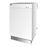
Electrical
connection socket
Service
switch
Boiler
thermostat
Pressure
gauge
Boiler On / Off switch Indicator lights
Overheat reset button
(under black cap)
10 Commissioning
It is important that the following
commissioning procedure is carried out
to ensure safe and efficient operation of
the boiler.
To access the controls, remove
the front panel (turn the handle and
withdraw it forwards at the bottom).
The controls are shown in Figure 10-1.
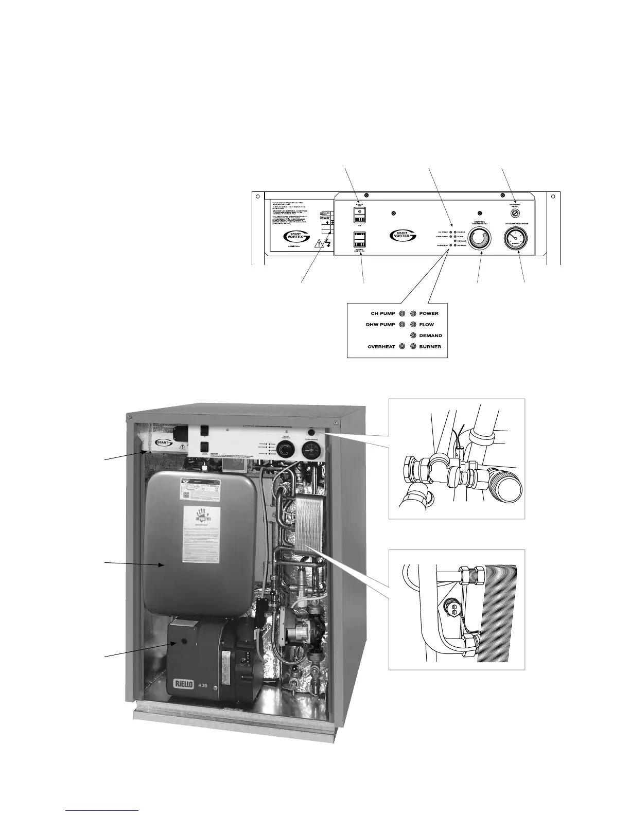
Figure 10-2: Vortex Pro Combi 21e boiler with
front panel removed showing position of control
panel
Figure 10-1: Vortex Pro
External Combi e boiler
control panel
Control
panel
Expansion
vessel
Burner
lock-out
button
Flow sensor (black sleeve)
Store sensor (white sleeve)