49
A High Efficiency Circulating Pump
selector knob at a pressure that
represents the maximum pressure
(head) loss for the heating system in
question.
Fault Diagnosis
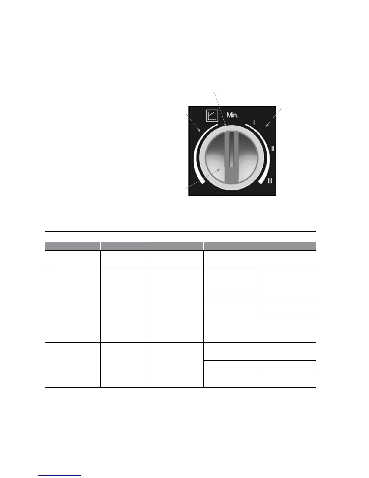
The Indicator LED, located around the
circumference of the red control knob,
can assist in diagnosing and rectifying
a fault with the pump. See the table
below.
Constant Speed
Mode settings:
I, II, III
Indicator LED
Variable Pressure
Mode settings:
1 to 7m head
Red selector knob
Figure A-2: Control panel with red selector knob and LED indicator
Table A-3: Fault diagnosis
LED condition Meaning Diagnostic Cause Remedy
Green Pump operating
Pump runs according to the
red knob setting
Normal operation N/A
Flashes Red and Green
Pump is operating but
stopped
Pump restarts by itself after
fault has disappeared
Undervoltage
Voltage<160V
OR
Overvoltage
Voltage>253V
Check supply
voltage is
195V<V<253V
Overheating:
temperature
inside motor too
high
Check water and
ambient
temperature
Flashes Red Pump not operating Pump stopped (blocked)
Pump does not
restart itself due
to a permanent
failure
Replace pump
LED off No power supply
No voltage to pump control
electronics
Pump is not
connected to
power supply
Check cable
connection
LED is damaged
Check if pump is
running
Electronics are
damaged
Replace pump
RECYCLING & DISPOSAL
This circulating pump must not be
disposed of in normal domestic waste
as most of the materials used in it’s
construction can be recycled. For
details on how to responsibly dispose of
this pump please go to:
www.wilo.com/recycling.