Do you have a question about the Grant SAP Series and is the answer not in the manual?
Contact information for Grant Instruments service department.
Guidelines for qualified personnel performing maintenance and repairs.
Defines the meaning of CAUTION and WARNING statements used in the manual.
Outlines electrical safety requirements and precautions for the water bath.
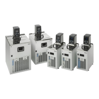
Details the available models and serial number ranges covered by this manual.
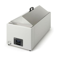
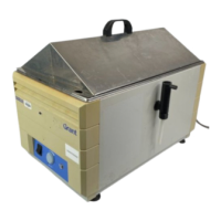
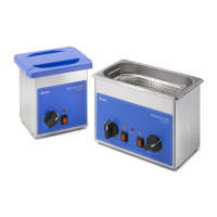
Describes the general construction and major component parts of the water bath.
Provides instructions and lists tools required for disassembling the water bath unit.
Step-by-step guide for safely removing the base plate from the unit.
Instructions for disconnecting and removing the tank, heater, and probe assembly.
Details the process for disconnecting and removing the Control and Display PCB.
Procedure for safely detaching and removing the front panel membrane keypad.
Guidelines for reassembling the unit, ensuring correct component seating and connections.
Presents the electrical schematic and interconnect diagram of the system.
Procedure to reset the over-temperature cut-out when triggered.
Steps for replacing the entire tank, heater, and probe assembly.
Instructions for identifying, testing, and replacing fuses on the PCB.
Guide for replacing the Control and Display PCB assembly with a new unit.
Lists the essential test equipment and tools needed for fault finding.
Overview of the process for diagnosing faults and verifying functionality post-repair.
A flowchart to guide users through systematic troubleshooting of common issues.
Provides typical resistance values for key components for diagnostic purposes.
Procedures for conducting essential electrical safety tests after repairs.
Method for verifying the integrity of the unit's earth connection.
Procedure for testing the electrical insulation of the unit.
Recommendations for performing periodic electrical safety and performance tests.
Explanations of the various messages that can be displayed by the unit.
Details the meaning of normal operational messages shown on the display.
Lists and explains fault and diagnostic messages indicating errors or conditions.
| Speed range | 30 - 300 rpm |
|---|---|
| Temperature Range | Ambient +5°C |
| Shaking Speed | 20-300 rpm |
| Material | Stainless steel |
| Power Supply | 50/60Hz |
| Timer | 0-999 minutes |