8
Grant Vortex External Module
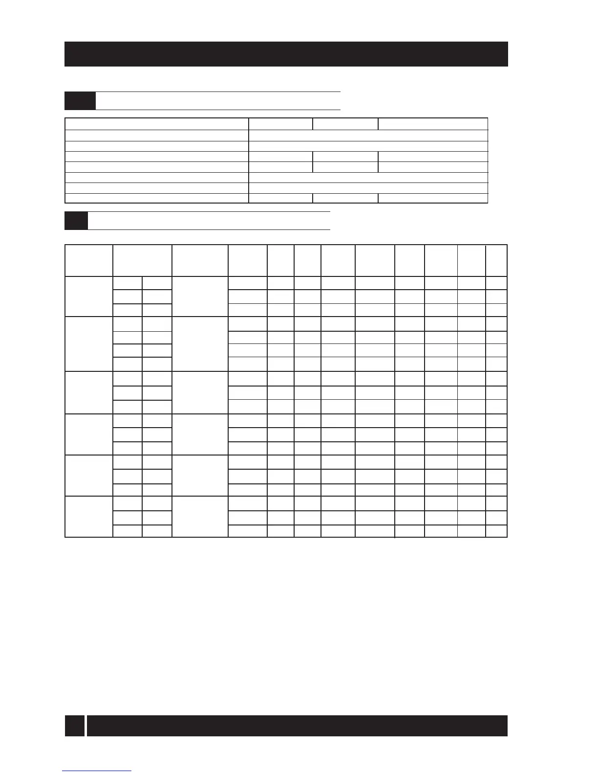
3 - BOILER TECHNICAL INFORMATION
Note: Grant Vortex External modules are only for use with kerosene.
Grant Vortex External modules using Class C2 kerosene
3.3
Sealed system data - none available for 155/200, 200/240
3.2
Notes:
1 The data given above is approximate only.
2 The above settings may have to be adjusted on site for the correct operation of the burner.
3 Gas Oil is not suitable for use with the Grant Vortex boiler range.
4 The net flue gas temperatures given above are ± 10%.
5 When commissioning the air damper must be adjusted to obtain the correct CO
2
level.
6 * Factory settings.
7 The combustion door test point may be used for CO
2
and smoke readings only. Do not use this test point for temperature or efficiency readings.
8 When setting the 50/90 to 51,200 or 68,240 Btu/h output or the 120/155 to 123,000 Btu/h output the combustion head must be changed. Refer to Section
7 Commissioning.
When setting the 50/70 to 51,200 Btu/h output the burner air adjuster disc requires repositioning. Refer to Section 9.4 Cleaning the burner.
9 The installer must amend the boiler data label if the output is changed.
Flue gas analysis
To allow the boiler to be commissioned and serviced, the boiler is supplied with a combustion test point on the front cleaning door. When this test point is
used please note the following:
1. The test point is for CO
2
and smoke readings only.
2. The boiler efficiency and temperature must be taken from the flue test point on high level and vertical flue adaptors.
3. Low level flues do not contain a test point. The temperature and efficiency readings must be taken from the flue terminal.
(kW)
15.0
18.3
21.0
15.0
20.0
23.0
26.0
26.0
31.5
36.0
36.0
41.5
46.0
46.0
52.0
58.0
58.0
64.0
70.0
(Btu/h)
51,200
62,400
71,650
51,200
68,240
78,500
88,700
88,700
107,500
123,000
123,000
141,600
157,000
156,952
177,424
197,896
197,896
218,368
238,840
Nozzle
0.50/80°EH
0.55/80°EH
0.60/80°EH
0.50/80°EH
0.60/80°EH
0.65/80°EH
0.75/80°EH
0.75/80°EH
0.85/80°EH
1.00/80°EH
1.00/80°EH
1.20/80°S
1.25/80°S
1.25/80°S
1.35/80°S
1.65/80°S
1.65/80°S
1.65/80°S
1.75/80°S
Oil
press.
(bar)
7.0
7.5
9.0
7.0
8.0
8.5
8.0
8.0
9.0
9.1
9.0
8.0
8.0
8.0
9.5
8.0
8.0
9.5
9.5
Smoke
No.
0 - 1
0 - 1
0 - 1
0 - 1
0 - 1
0 - 1
0 - 1
0 - 1
0 - 1
0 - 1
0 - 1
0 - 1
0 - 1
0 - 1
0 - 1
0 - 1
0 - 1
0 - 1
0 - 1
Fuel flow
rate
(kg/h)
1.29
1.56
1.83
1.25
1.67
1.94
2.18
2.18
2.57
3.01
3.01
3.56
3.90
4.01
4.47
5.05
5.05
5.58
6.01
Flue gas
temp.
(°C)
66
73
80
60 - 65
65 - 70
70 - 75
68
68
70
78
78
80
88
75 - 80
75 - 80
75 - 80
75 - 80
75 - 80
75 - 80
CO
2
(%)
12.0
12.0
12.0
12.0
12.0
12.0
12.0
12.0
12.0
12.0
12.0
12.0
12.0
12.0
12.0
12.0
12.0
12.0
12.0
Burner
head type
T1
T1
T1
T1
T1
T2
T2
T3
T3
T3
T3
T5
T5
GIB
GIB
GIB
GIB
GIB
GIB
Heat Output
50/70
Riello RDB2.2
50/90
Riello RDB1
90/120
Riello RDB2
120/155
Riello RDB2.2
155/200
Riello RDB3.2
200/240
Riello RDB3.2
Model and
burner type
*
*
*
HARP/SEDBUK
efficiency
(%)
93
94 - 95
97
92.62
94.1
93.6
*
Air disc
position
B
C
C
-
-
-
-
-
-
-
-
-
-
-
-
-
-
-
-
*
*
Maximum 1.0 bar, Minimum 0.5 bar
2.5 bar
15 mm copper pipe
15 mm copper pipe
Model
Heating system pressure (cold)
Operating pressure of pressure relief valve
Expansion vessel size (approximately)
Max heating system volume (including boiler)
Cold water mains connection
Pressure relief valve discharge connection
Circulating pump head
50/70
10 litres
106 litres
6 m
50/90
12 litres
128 litres
6 m
90/120 and 120/155
16 litres
170 litres
7 m
Burner
head setting
Fixed
Fixed
Fixed
Fixed
Fixed
Fixed
Fixed
Fixed
Fixed
Fixed
Fixed
Fixed
Fixed
0
0
0
0
0
4