EasyManua.ls Logo

Grasshopper 600 Series - Clutch Removal;Replacement.0; Clutch;Brake Bumishing; Engine Troubleshooting; Engine Removal

Grasshopper 600 Series
44 pages
Print Icon
To Next Page IconTo Next Page
To Previous Page IconTo Previous Page
Loading...
Disconnect
the
left
brake
linkage
rod
and
adjust
the
linkage
pin
attached
to
the
right
brake
until
it
takes
5
to
6
lbs.
of
pull
at
the
top
of
the
hand
lc-
ver
to
apply
the
parking
brake.
Connect
the
left
brake
linkage.
Be
sure
all
cotter
pins
and
jam
nuts
arc
secured.
CLUTCH
REMOVAL
/REPLACEMENT
1.
Remove
two
carriage
bolts
(item
21,
page
25).
Lift
out
weight
cover
and
rear
weights.
2.
Remove
anti-rotation
bracket
(item
17,
page
30).
3.
Looscn
spring
tension
(item
30,
page
30)
on
drive
belt
idler
pulley
and
remove
drive
belts
(item
11,
page
30).
4.
Unplug
wires
from
clutch
and
remove
center
bolt
(item
20,
page
30).
Slide
clutch
off
en-
gine
crankshaft.
5.
Reverse
order
to
install
new
clutch.
CLUTCH
/
BRAKE
BURNISHING
IMPORTANT
A
new
clutch,
or
one
that
has
not
been
used
for
three
months,
will
require
burnishing
to
dress
drive
surfaces.
The
clutch
could
fail
if
you
do
not
accomplish
the
following
procedure.
Place
tractor
in
neutral and
start
engine.
Turn
clutch
switch
on
30
seconds
and
off
30
scconds,
five
times
at
half-throttle
and
repeat
five
times
at
full
throttle.
The
time
interval
allows
the
clutch
surface
to
cool.
ENGINE
TROUBLESHOOTING
Should
you
experience
trouble
in
starting
the
cn-
gine,
use
the
following
guide
to
locate
possible
causes.
Engine
will
not
crank:
«
Battery
is
discharged.
e
Blownstarter
fuse.
e¢
PTO
switchis
“ON”.
«
Steering
levers
are
not out
in
neutral.
20
e
Steering
lever
switches
are
out
of
adjustment
(listen
for
the
switch
“click”).
e
A
loose
wire
or
connection.
Engine
cranks,
but
will
not
start:
e
Fuel
tank
is
empty.
e
Restricted
fuel
line
or
fuel
filter.
e
A
loose
wire
or
connection.
If
the
above
points
do
not
locate
the
problem,
contact
your
authorized
Grasshopper
dealer
for
repair.
ENGINE
REMOVAL
To
remove
engine,
disconnect:
battery,
fuel
line,
electrical
wires
from
engine,
throttle,
choke
and
flex
coupling
to
drive
spindle
housing.
Remove
the
four
engine
mount
bolts
to
the
frame
and
drive
belts
from
clutch
sheave.
The
engine
can
now
be
lifted
out.
Consult
your
local
authorized
engine
dealer
for
repairs
or
repair
parts.
WIRING
CIRCUIT
BOARD
REMOVAL
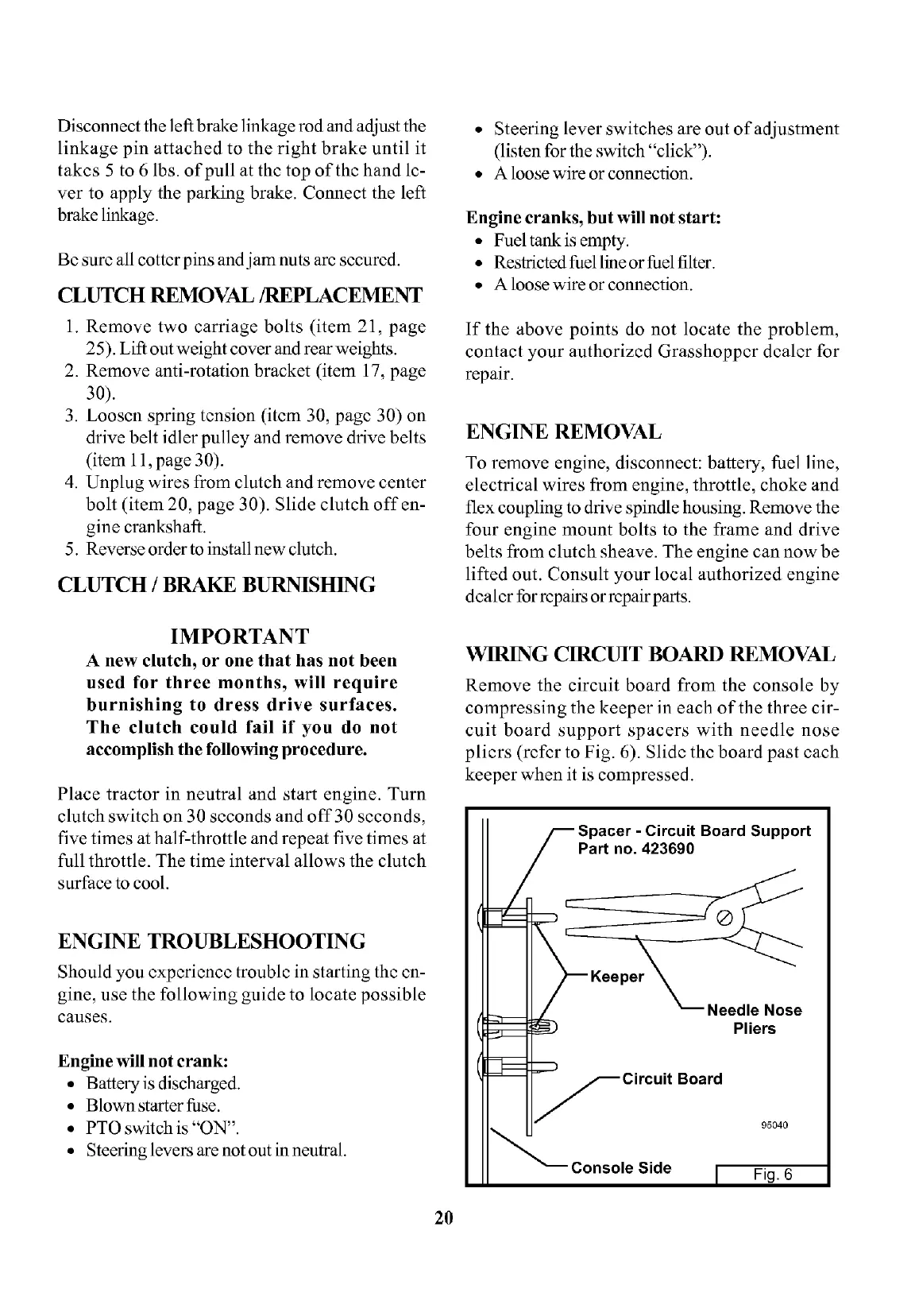
Remove
the
circuit
board
from
the
console
by
compressing
the
keeper
in
each
of
the
three
cir-
cuit
board
support
spacers
with
needle
nose
plicrs
(refer
to
Fig.
6).
Slide
the
board
past
cach
keeper
when
it
is
compressed.
Spacer
-
Circuit
Board
Support
Part
no.
423690
Needle
Nose
Pliers
LO
Board
95040
Console
Side
|
Fig.
6

Table of Contents