8
MODELS 720, 721, AND 725.
1. Control relay - inspection.
A. Control relay A has 2 red wires, 1
black wire, and 1 yellow wire in the
relay socket.
B. Control relay B has 3 blue wires and
1 yellow wire in the relay socket.
2. Assuming the main fuse, PTO fuse,
ignition fuse are good, failure of control
relay A or associated wiring will be
evidenced by the following three symp-
toms:
A. PTO clutch will not engage.
B. Hourmeter will not run.
C. Ignition coil will not have any volt-
age on the positive terminal.
3. Assuming the start fuse is good, failure
of control relay B or associated wiring
will result in starter solenoid not engag-
ing; thus the starter motor will not
operate.
MODELS 718D AND 721D.
1. Control relay - inspection.
A. Control relay A has 2 red wires, 1
black wire, and 1 yellow wire in the
relay socket.
B. Control relay B has 3 blue wires and
1 yellow wire in the relay socket.
2. Assuming the main fuse, PTO fuse,
ignition fuse are good, failure of control
relay A or associated wiring will be
evidenced by the following three symp-
toms:
A. PTO clutch will not engage.
B. Hourmeter will not run.
C. Fuel solenoid will pull in but not
hold.
3. Assuming the start fuse is good, failure
of control relay B or associated wiring
will result in starter solenoid not engag-
ing; thus the starter motor will not
operate.
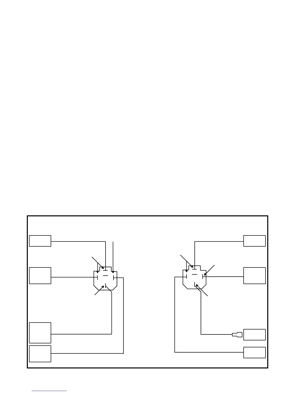
TROUBLESHOOTING CONTROL RELAYS
Figure 1
A
B
Blue
Red
Blue
Black
Yellow
Red
Yellow
Blue
+12 volts with key
sw i t c h i n 'START'
position
This wire goes to
ground with steering
levers out and PTO off
+12 volts when relay
'B' is e n e r gi ze d
+12 volts
with key
switch in
'RU N '
position
+12 volts when relay
'A' is energized
This wire goes to ground when:
1. Driver on seat and parking brake released,
2. or PTO off, both steering levers out,
3. or both of the above.
To main
fuse
To pad
M of PC
board
To pad
A of PC
board
To PTO
fuse &
ignition
fuse
To start
fuse
To start
fuse
To pad
R of PC
board
Starter
solenoid