12 / 20 13 / 20
S1012_GR-12L_DE_V1sh S1012_GR-12L_DE_V1sh
Setting and display of the receiver settings
The receiver-side menus can be viewed and sometimes changed
using a suitable HoTT transmitter or the SMART-BOX. You can find
out how to open the menus of a receiver in the "Telemetry" section
of the corresponding manual as well as a detailed description of the
receiver menus on the respective product page at www.graupner.
de on the Internet.
Note
The values shown in the following display illustrations always show
the standard values.
Display "RECEIVER"
ALARM VOLT
• If "SERVO" or "SENSOR" is visible in the "CH5 FUNCTION" line
described below, the operating voltage of the receiver is moni-
tored via the limit value set in the value field of "ALARM VOLT".
• If "BATT-V" is visible in the "CH5 FUNCTION" line described below,
the operating voltage of the drive battery connected via "BATT-V"
is monitored via the limit value set in the value field of "ALARM
VOLT".
In both cases, the actual voltage is shown in the transmitter's display
in the "Receiver voltage" field.
If the voltage drops under the set limit value, a transmitter-side
alarm takes place in the form of an acoustic signal (interval beep long
/ short).
Adjustment range: 2,5 … 22,5 Volt in 0,1 Volt steps.
ALARM TEMP
This option monitors the receiver temperature. If the set limit is
exceeded, a transmitter-side alarm takes place in the form of a con-
tinuous beep.
Adjustment range: 30 … 80 °C
PERIOD
In this line, specify the periods for the individual channel pulses. This
setting is transferred for all control channels.
If your system is used exclusively with digital servos, you can set a
cycle time (frame rate) of 10 ms. If your system includes some or
uses exclusively analogue servos, always select 20 ms since the ana-
logue servos may be overloaded and respond by "jittering" or "growl-
ing".
Adjustment range: 10 or 20 ms
TELEMETRY
SETTING & DATA VIEW
SENSOR
DISPLAY RF STATUS
SELECT ANNOUNCE
RX DATA ON
ALARM SETTING
RECEIVER 2.05
ALARM TEMP: 65°C
ALARM VOLT: 3.7V
CH5 FUNCTION:SERVO
PERIOD: 20ms
RSSI CH : OFF
CH6 FUNCTION:SERVO
F.RESET : No
CH5 FUNCTION
• SERVO
Port "5" is suitable for operating RC components and for receiver
updates.
• SENSOR
Port 5 is suitable for the operation of telemetry sensors.
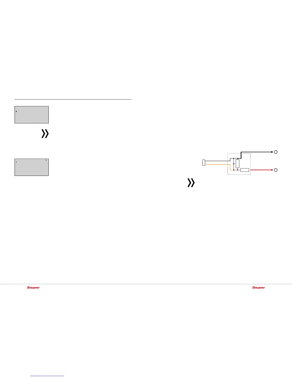
• BATT V
After switching as described before, a DC voltage off max. 25,5 V
can be displayed instead of the receiver voltage. This way it is
possible to monitor the main battery voltage without using exter-
nal sensors. The ESCs S3082 and S3083 have this switch already
included.
–
+
Attention
Never connect a power supply with an output voltage higher than
8,4 V directly to a connection port of the receiver! The receiver and
all connected devices would be immediately destroyed.
CH6 FUNCTION
• SERVO
The connection 5 is suitable for the operation of RC components.
• SUMD
At connection 5, a digital sum signal is provided.
• SBUS
Digital sum signal in SBUS format.
• SP2018
The port 6 is suitable for connecting a flight control, the Spektr.
2048 signal can handle. e.g. 48377.
RSSI CH
As soon as "SUMD", "SBUS" or "SP2048" is selected instead of
"SERVO" in the "CH6 FUNCTION" line described above, changing the
value field of this option from "OFF" to "CHxx" will change the num-
ber of channels contained in the selected sum signal. At the same
time, the servo signal of the highest numbered channel is replaced
by an RSSI signal.