21General operating notices
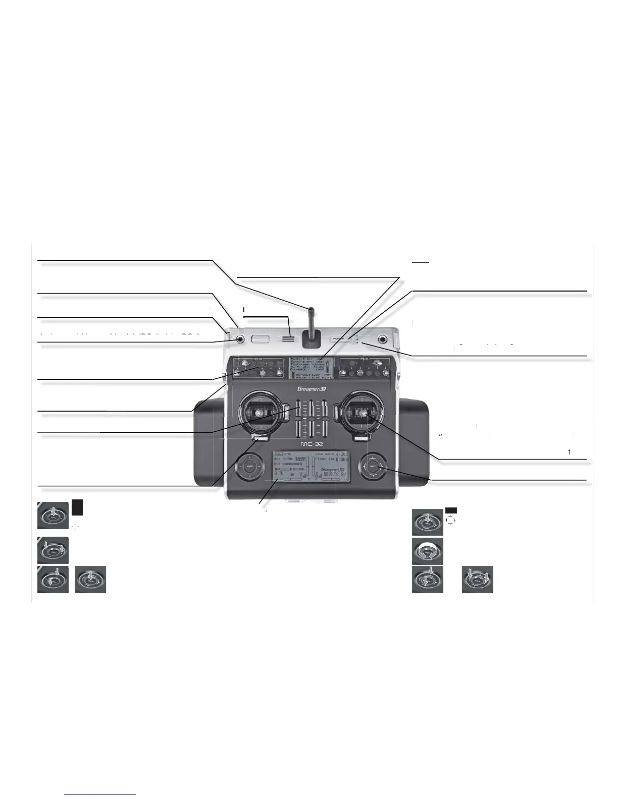
Transmitter description
Front side
Antenna
removable antenna, with kink and twist joint
Option locations
for retrofi tting the transmitter with switches and knob
modules 8 switches included as standard equipment
Function modules
three sliders, "SR1", "SR2", "SR3"
Digital trim
For the fi ne-tuning of servo positions
(travel neutralization). When turned, each click
produces an increment of adjustment (position
indicator in display). A press on the trim wheel
will reset the trim adjustment.
LC Display (more details available on page 28.)
Contrast adjustment: a simultaneous tap on
() + "SET" of the right touch pad = change
to "secret options"
Warning indicators:
for underrun of preset battery voltage threshold•
for fault function of the teacher/pupil system•
C1 joystick too far toward full throttle when •
transmitter is switched on
…•
ON/OFF switch (ON/OFF with LED display)
Note:
Always switch on the transmitter then the receiver.
When switching off, fi rst switch off the receiver then
the transmitter.
Joystick
Two joysticks for a total of four independent
control functions. The length of the joysticks can
be adjusted. The correlation of control functions
1 … 4 can be set on a model type basis by
way of the »Basic settings, model« and
»Control adjust« menus, e.g. throttle left or
right. The throttle joystick can be converted from
neutralizing to non-neutralizing, see page 19.
touch sensitive keys, left and right
LC Display (more details available on page 28.)
Telemetry indicators: receiver parameters,
standard. Other indicators dependent on the
data from the optional sensors connected.
LED indicators
BATTERY: illuminates when voltage is suffi cient
RF: illuminates during RF radiation
WARNING: blinks, for example, when "Throttle too
high", "no pupil signal", "Transmitter
battery voltage too low", …
Function module
rotary control: left-side "SD2",
right-side "SD1"
Function modules
Drum roller control: left "DG5", top "DG3", right "DG1"
Function modules
Knob control (depressible): left "DG4", right "DG2"
Loudspeaker
left touch pad:
+
SET = select/confi rm
SET touched for about 1 s: Changeover between
telemetry menu and basic display
= scroll in one of the four directions with every
tap (, , , )
simultaneous horizontal tap ()
= changeover between basic display and servo
display
simultaneous vertical tap of the left
() keys + "SET" of the right touch
pad = changeover to the "secret
options", see page 32.
SET = select/confi rm
= scroll or change value with every touch of one
of the four direction
symbols (, , , )
Circle with the fi nger around the circumference
= scroll/change values. Alternative values
selection with the left touch pad (, , , )
simultaneous tap on
or = CLEAR
right touch pad:
or
 Loading...


