296 Programming examples - Using fl ight phases
Now we will program the required settings in the
fl ight phase "Thermal" as an example.
In order to vary camber fl ap positions in the
«Thermal» phase, it is merely necessary to switch
over to the menu …
»Control adjust« (page 108)
… then change Input 6 – as described beginning on
page 108 – from "GL(obal)" to "PH(ase)" and fi nally
assign it to an operating element.
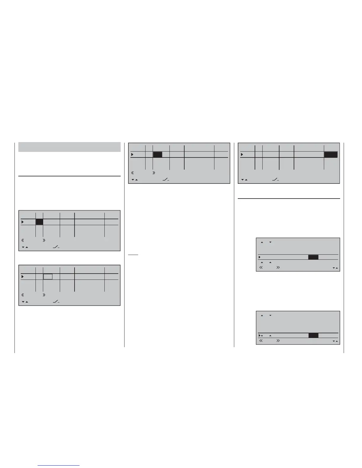
To do this, fi rst use the selection keys to switch into
the "Typ" column for "I6" and change this setting from
"GL" to "PH".
0%
+100%I5
I6
I7
I8
Typ
+100%
0.0 0.0
– travel + –time+
0%
+100%
+100%
0.0 0.0
0%
+100%
+100%
0.0 0.0
0%
+100%
+100%
0.0 0.0
GL
GL
fr
Cn1
fr
---
---
---
offset
GL fr
Thermal
PH
---
SEL
Thereafter change one column to the right into the
column above SEL …
0%
+100%I5
I6
I7
I8
Typ
+100%
0.0 0.0
– travel + –time+
0%
+100%
+100%
0.0 0.0
0%
+100%
+100%
0.0 0.0
0%
+100%
+100%
0.0 0.0
GL
GL
fr
Cn1
fr
---
---
---
offset
GL fr
PH
---
SEL
Thermik
… and now assign this input, as described in the
section "Assigning transmitter controls, switches and
control switches" on page 56, the left proportional
slider in the middle console to, for example:
0%
+100%I5
I6
I7
I8
Typ
+100%
0.0 0.0
– travel + –time+
0%
+100%
+100%
0.0 0.0
0%
+100%
+100%
0.0 0.0
0%
+100%
+100%
0.0 0.0
GL
GL
Cn1
fr
---
---
---
offset
GL fr
PH
---
SEL
Sl1
Thermal
This control will allow the ailerons (2 + 5) and camber
fl aps (6 + 7) to be continuously adjusted (as camber
fl aps) with a mixer ratio yet to be set via the »Wing
mixers« menu.
If you assign the still free second three-stage switch
to Input 6 instead, you can call three different FL
positions of the ailerons (AIL) and camber changing
fl aps (FL) as well as three elevator positions (Elev)
in the "Thermal" fl ight phase, see the following
page. (These three switch positions correspond to
the center position and the two limit positions of the
previously mentioned proportional rotary control.)
Note:
The FL and AIL fl ap positions in the two limit switch
positions or in the switch center depend on the value
set in the column "- Travel +" as well as the offset
value and the mixer proportion set in the "Multi-fl ap
menu" of the »Wing mixers« menu, see further
below.
Leave the (control) "- travel +" at its standard
symmetric settings of + 100 % and the offset value at
0 %. Specifying a symmetric or asymmetric time for
smooth switching between the three switch positions
- in the example "1.0 s 1.0 s" - in the column "- Time
+" is recommended:
0%
+100%I5
I6
I7
I8
Typ
+100%
0.0 0.0
– travel + –time+
0%
+100%
+100%
0%
+100%
+100%
0.0 0.0
0%
+100%
+100%
0.0 0.0
GL
GL
Cn1
fr
---
---
---
offset
GL fr
Normal
PH
---
SEL
Sl1
1.0 1.0
In the "Multi-fl ap menu" of the …
»Wing mixers« (beginning page 160)
… menu, subsequently change only the values for
"FL.pos" and "FL" in the «Thermal» fl ight phase:
FL.pos It is here that AI and FL positioning takes
place during the «Thermal» fl ight phase
in the event that the assigned control
(proportional control or 3-way switch) is in
its neutral or middle position.
FL.pos
Diff.
Ail-tr.
AI
Thermal AI
+100%
WK2
FL
0%
+66%
0%
+100%+100%
–9%
+100%
+33%
0%
+33%0%
+100%
+66%
0%
0%
FL
+100%
0%
+100%
–11%
FL Enter in this line the the share of infl uence
for aileron and camber fl ap servos, when
used as camber fl aps, is to be produced by
the selected control (see above) or 3-way
switch. Be sure to set these values high
enough that the fl aps can be controlled with
appropriate sensitivity, for example:
Fl.pos
Diff.
AiI-tr.
AI
Thermal AI
+100%
WK2
FL
0%
+66%
0%
+100%+100%
–9%
+100%
+33%
0%
+33%0%
+100%
+66%
0%
0%
FL
+20%
+25%
–11%
+25%
+20%

 Loading...


